Apparatus and method for measuring quality of image received via communication network

a technology of communication network and image, applied in the field of apparatus and method for measuring the quality of an image received via a communication network, can solve the problems that the development of such a technology has not been achieved

Active Publication Date: 2008-06-12
INNOWIRELESS
View PDF3 Cites 21 Cited by
  • Summary
  • Abstract
  • Description
  • Claims
  • Application Information

AI Technical Summary

Benefits of technology

[0008]Accordingly, the present invention has been made keeping in mind the above problems occurring in the prior art, and an object of the present invention is to provide an apparatus and method for measuring the quality of a...

Problems solved by technology

However, there is a problem in that the ...

Method used


Image

  • Apparatus and method for measuring quality of image received via communication network
  • Apparatus and method for measuring quality of image received via communication network
  • Apparatus and method for measuring quality of image received via communication network

Examples


embodiment 1

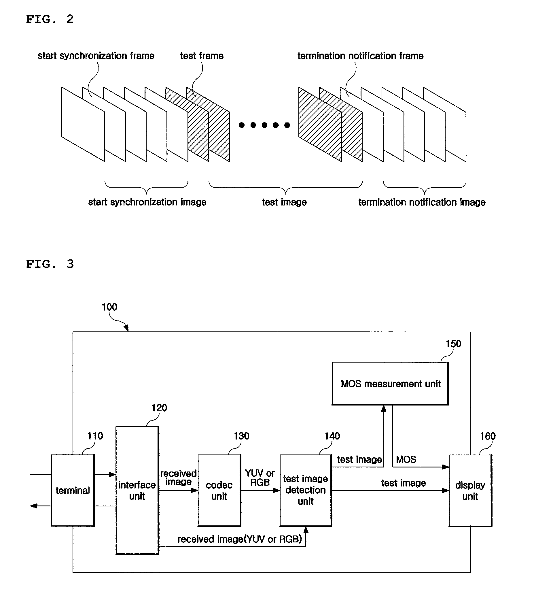
[0031]FIG. 2 is a diagram showing the frame structure of an image for the measurement of quality according to an embodiment of the present invention. As shown in FIG. 2, the structure of a received image input to the image quality measurement apparatus 100 includes a ‘start synchronization image’ for the synchronization of the start of a quality test, an actual ‘test image,’ and a ‘termination notification image’ for the provision of notification of the termination of a test. Here, the start synchronization image must significantly differ from the test image in brightness, hue or saturation. For example, the start synchronization image may be made to be distinguished from the test image by setting white color information for all of the pixels of the frames of the start synchronization image.

[0032]FIG. 3 is a block diagram showing the functional module configuration of an apparatus for measuring the quality of an image according to an embodiment of the present invention.

[0033]As show...

embodiment 2

[0044]FIG. 5 is a diagram showing the frame structure of an image for quality measurement according to another embodiment of the present invention. As shown in FIG. 5, each frame (hereinafter referred to as a “test frame”), constituting part of a test image input to the image quality measurement apparatus 100, is provided with a recognition mark at a predetermined location, preferably in outermost pixels of the test frame, so as to distinguish the test frame from the other test frames. Here, it is preferred that the recognition mark be marked in each test frame in the form of a serial number. For example, when 5 pixels are set for 1 bit, as shown in FIG. 2, 4 bits, that is, 20 pixels, are assigned to one recognition mark. Furthermore, the number of recognition marks marked in a test frame may be freely determined according to the type of communication network. That is, in the case where the present invention is applied to a communication network the data transmission status of which...


PUM


Abstract

Disclosed herein are an apparatus and method for measuring quality of an image received via a communication network. The apparatus includes an interface unit, a codec unit, a test image detection unit, and a Mean Opinion Score (MOS) measurement unit. The interface unit receives an image, including a start synchronization image and a test image via a communication network. The codec unit decodes the received image into a color signal. The test image detection unit detects any one value of brightness, saturation and hue information of the color signal input from the codec unit, calculates an average value for each frame, and detects the test image from the received image based on the calculated average value. The MOS measurement unit synchronizes the test image with a corresponding reference image, compares the quality of the test image with the quality of the reference image, calculates an MOS value based on the results of the comparison, and outputs the MOS value.

Description

CROSS REFERENCE TO RELATED APPLICATIONS[0001]This application claims priority from Korean patent application No. 10-2006-0116483 filed on Nov. 23, 2006, and Korean patent application No. 10-2007-0008929 filed on Jan. 29, 2007, all of which are incorporated herein by reference in their entireties for all purposes.BACKGROUND OF THE INVENTION[0002]1. Field of the Invention[0003]The present invention relates generally to an apparatus and method for measuring the quality of an image received via a communication network and, more particularly, to an apparatus and method for measuring the quality of an image received via a communication network, which is capable of measuring the quality of a test image by comparing the quality of the test image, received via the communication network, with the quality of a corresponding reference image, thereby inspecting the transmission / reception status of image data via the communication network.[0004]2. Description of the Related Art[0005]Recently, wit...

Claims


Application Information

Patent Timeline
IPC IPC(8): G06K9/68
CPCH04N17/004
Inventor JOUNG, JINSOUPKWAK, YOUNG SUKIM, JIN MANJEONG, JIN SAMLEE, JAE HWAN
Owner INNOWIRELESS
Why Eureka
Try Eureka