Apparatus for measuring a structure and associated method

a technology for measuring apparatus and structures, applied in the direction of excavation, bulkhead/pile, reradiation, etc., can solve the problems of hardly maintaining a desired level of quality, damage situation, and significant increase in the effort and expense of structural inspection underwater, so as to increase the operational speed of the bearing platform, increase the spacing between the measurement sensor and the structure, and improve the effect of measurement quality

Inactive Publication Date: 2021-03-11
HYDROMAPPER GMBH
View PDF0 Cites 0 Cited by
  • Summary
  • Abstract
  • Description
  • Claims
  • Application Information

AI Technical Summary

Benefits of technology

[0019]Also, according to one embodiment, if the at least one quality reference value is achieved beyond requirements, one or more additional quality characteristics indicating measurement quality can be optimized. Here, optimization is understood as the additional quality characteristic(s) being adapted such that in total a desired level of quality or best possible quality is achieved. For example, the spacing of the measurement sensor with respect to the structure can comprise 3 m although a spacing of 5 m would be possible to maintain a quality target of 2 cm for resolution. The spacing between measurement sensor and structure can then be enlarged and / or the operational speed of the bearing platform increased to facilitate faster recording (an additional quality characteristic) and to be able to release the structure to be investigated faster once again. Thus the quality characteristic for “recording time” can also be optimized. In another example, the accuracy is better required as a first quality characteristic than by the corresponding quality reference value. Completeness as a second quality characteristic can then be increased by more time-consuming inspection of the structure, or the recording time can be reduced by greater operational speed of the bearing platform. The converse applies likewise.
[0027]According to one embodiment, the at least one measurement sensor comprises at least one sensor emitting electromagnetic radiation or soundwaves, in which the orientation of the sensor with respect to the structure occurs such that the radiation or soundwaves emitted by the sensor strike the surface of the structure at a defined angle, in particular perpendicularly. The measurement sensor can be a laser scanner, for example, which directs laser radiation in an essentially linear manner onto the structure and detects laser radiation reflected by the structure. The inventive regulation can also take place here for orientation as a parameter so the laser beam impinges perpendicularly on the surface of the structure to record, i.e. of the structure. Skewed angles of incidence, which, as explained, can result in high noise in the structural data and in particular poor resolution of the structural data, are thus avoided. However, for particularly smooth surfaces it can be expedient to avoid perpendicularly incident radiation, because this can result in excessive radiation input to the sensor. Thus an angle deviating from a right angle can be particularly envisaged.

Problems solved by technology

Structural inspection underwater is associated with significantly greater effort and expense.
It is in particular hardly possible to maintain a desired level of quality for the measurement, because the characteristics influencing quality cannot be controlled.
Subjective perceptions result in a damage situation, damage classification and damage trends which are not reproducible in routine structural inspections.
What the known methods and measuring apparatuses have in common is that they cannot ensure sufficiently high quality of the data collected.
As the inventors have recognized, this is particularly due to the known methods and measuring apparatuses performing only uncontrolled measurement of the structure.
In fact, in some cases a level of quality to achieve is specified prior to measurement, but maintaining said level cannot be ensured.
This can lead in particular to variations in the quality of recordings which permit only an unreliable statement regarding damage found on the structure.
Known methods or measuring apparatuses respectively also cannot ensure reproducibility of the measurement with repeated recording of the structure.

Method used


Image

  • Apparatus for measuring a structure and associated method
  • Apparatus for measuring a structure and associated method
  • Apparatus for measuring a structure and associated method

Examples


Embodiment Construction

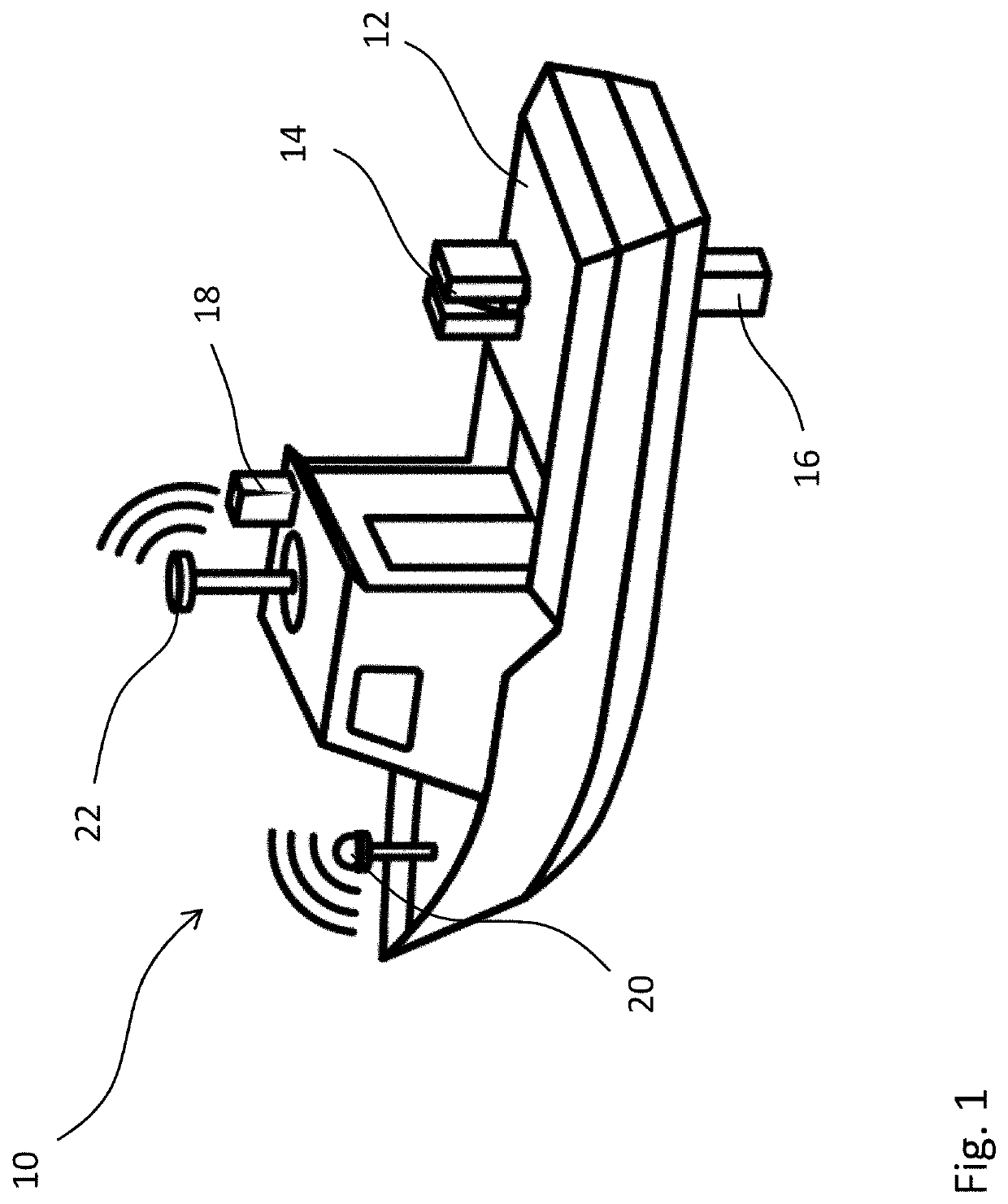
[0039]FIG. 1 shows an embodiment of a measuring apparatus 10 for measuring a port construction. The measuring apparatus 10 comprises a buoyant bearing platform 12 in the form of a boat, a scanner above water 14, a scanner below water 16, a camera 18 and a GNSS receiving unit 20. The scanners and camera 14, 16 and 18 include measurement sensors 14, 16, 18 that are used for measuring a structure. The measurement sensors 14, 16, 18 can be arranged in a manner not depicted on a shared sensor platform. Furthermore, a reflector 22 is situated on the bearing platform 12. The measuring apparatus 10 also has a drive, not shown and situated on the bearing platform, with which the bearing platform 12 is actively powered and thus able to be moved along a structure for a measurement run.

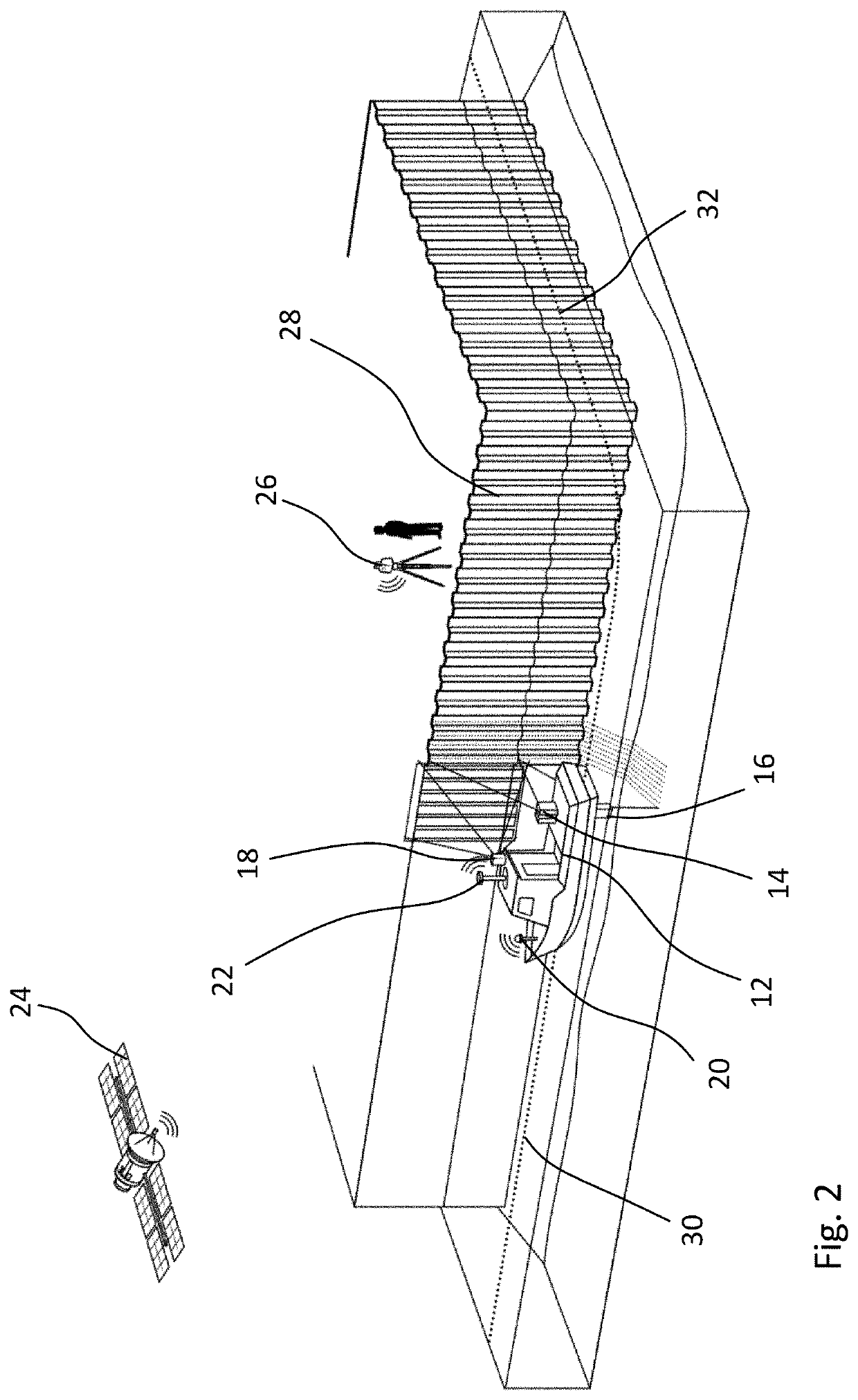
[0040]FIG. 2 shows the measuring apparatus 10 during measurement of a structure close to water, specifically a bulkhead 28 in the present case. There is also a tacheometer 26 situated on land. The tacheometer 26 ...


PUM


Abstract

A measuring apparatus for measuring a structure comprises at least one measurement sensor configured to measure the structure, a bearing platform configured to carry the at least one measurement sensor and a control. The control is configured to specify at least one quality reference value for at least one characteristic of measurement quality, and further configured to adjust one or more parameters of the measuring apparatus which influence the at least one characteristic of measurement quality. An actual quality value is determined and approaches the at least one quality reference value as the one or more parameters are adjusted.

Description

CROSS REFERENCE TO RELATED INVENTION[0001]This application is based upon and claims priority to, under relevant sections of 35 U.S.C. § 119, German Patent Application No. 102019124378.5, filed Sep. 11, 2019, the entire contents of which are hereby incorporated by reference.TECHNICAL FIELD[0002]The invention relates to a method for measuring a structure, in particular for purposes of damage assessment for the structure and construction monitoring. The invention also relates to a measuring apparatus for measuring the structure.BACKGROUND[0003]The exterior contour of the structure in particular can be determined by such measurement of a structure. It can, for example, be applied in a structural inspection, particularly to investigate the structure for damage and / or deformations. Such investigations are performed on structures of the most diverse kind to identify in a timely manner damage which could, for example, endanger the structural integrity of the construct, and to facilitate the...

Claims


Application Information

Patent Timeline
Patent Type & Authority Applications(United States)
IPC IPC(8): G01B21/20
CPCG01B21/20G01B11/24E02D5/02E02D17/04E02D33/00G01C15/00G01N29/221G01N29/225G01N2291/0232G01N2291/0258G01S15/89G01S17/89G01S15/86G01B17/06H04N7/18
Inventor HESSE, CHRISTIANHOLSTE, KARSTENNEUMANN, INGO
Owner HYDROMAPPER GMBH
Why Eureka
Try Eureka