Check patentability & draft patents in minutes with Patsnap Eureka AI!

Decoder, decoding method and computer readable medium

a decoding method and computer readable medium technology, applied in computing, instruments, electrical appliances, etc., can solve the problems of coders being required to perform coding processing conscious of resolution, the storage area of the second decoding procedure of the above described integrated circuit may have an upper limit to the size and the storage area of the above described integrated circuit may not have the upper limit of data that can be stored at a tim

Inactive Publication Date: 2008-06-12
KK TOSHIBA
View PDF8 Cites 0 Cited by
  • Summary
  • Abstract
  • Description
  • Claims
  • Application Information

AI Technical Summary

Benefits of technology

[0018]dividing the first data into a plurality of second data each

Problems solved by technology

However, on the other hand, the storage area for the second decoding procedure of the above described integrated circuit may have an upper limit to the size of data that can be stored at a time.
Therefore, in this case, when image data which exceeds this upper limit in size is inputted, the subsequent decoding processing can no longer be continued.
However, the above described method whereby the coder divides and codes image data according to a division scheme arranged between the coder and decoder beforehand and the decoder performs decoding and combining has a problem that the coder is required to perform coding processing conscious of resolution which can be processed by the decoder.
Therefore, even when the method described in JP-A 6-303594 (Kokai) is used for still image data sent out from the coder which has no means for data division, this still image data cannot be decoded.
In such a circumstance, when communication equipment or a communication system equipped with a coder and decoder is constructed, there is not only a problem that the degree of freedom of design is degraded but also a problem that it is difficult to maintain compatibility with an existing system.

Method used


Image

  • Decoder, decoding method and computer readable medium
  • Decoder, decoding method and computer readable medium
  • Decoder, decoding method and computer readable medium

Examples


Embodiment Construction

[0038]Hereafter, an embodiment of the present invention will be explained with reference to the attached drawings.

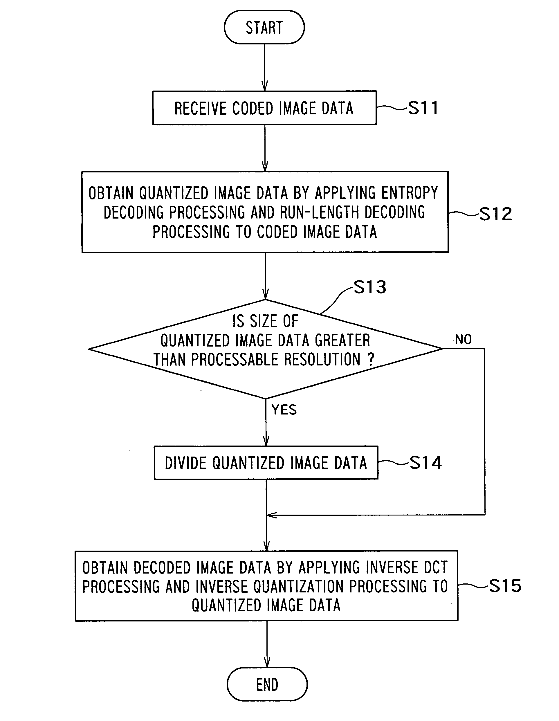
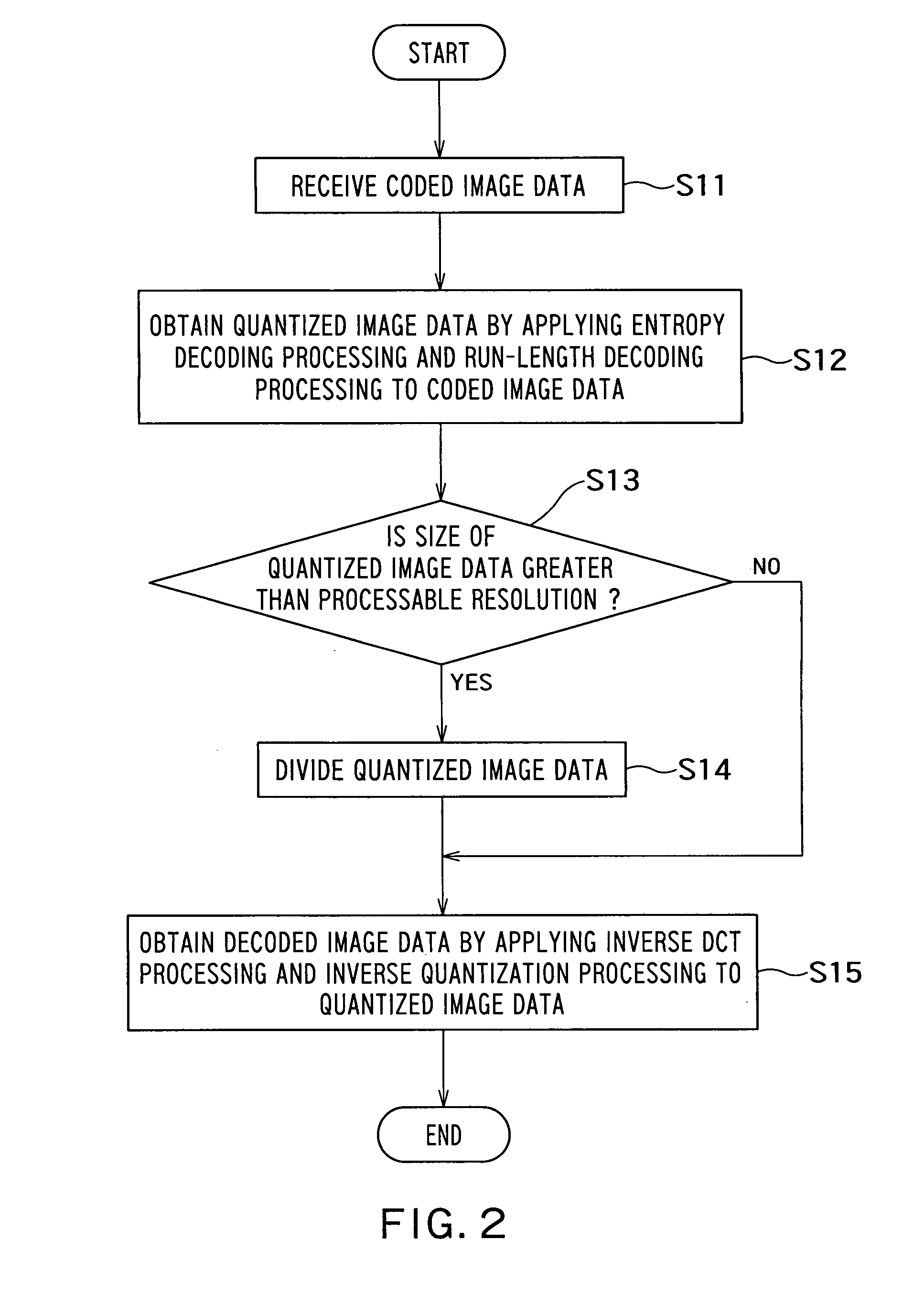
[0039]FIG. 1 shows the configuration of a decoder 1 as the embodiment of the present invention. The input side of the decoder 1 is connected to a coded image storage 2 and the output side is connected to a decoded image storage 3.

[0040]The coded image storage 2 has a storage area from which data can be read. This storage area stores image data before being decoded by the decoder 1, that is, coded image data. This coded image data is given resolution information indicating resolution (size) of an image before coding by the coder and output position information indicating a desired output position in the storage area of the decoded image storage 3. The set of the coded image data, resolution information and output position information is called “input information.” The input information is transmitted from the coder side and is received through an arbitrary network.

[0041]H...


PUM


Abstract

There is provided with a decoder which decodes coded image data obtained by applying entropy coding to first data obtained by applying a discrete cosine transform and quantization processing to image data, including: a first decoding unit configured to apply entropy-decoding to the coded image data to obtain the first data; a dividing unit configured to divide the first data into a plurality of second data each of which has a size equal to or smaller than a first threshold; and a second decoding unit configured to apply inverse quantization processing and inverse discrete cosine transform to each second data sequentially to obtain a plurality of third data, and a generating unit configured to generate the image data by synthesizing the plurality of third data.

Description

CROSS-REFERENCE TO RELATED APPLICATIONS[0001]This application is based upon and claims the benefit of priority from the prior Japanese Patent Applications No. 2006-301695 filed on Nov. 7, 2006, the entire contents of which are incorporated herein by reference.BACKGROUND OF THE INVENTION[0002]1. Field of the Invention[0003]The present invention relates to a decoder, a decoding method and a computer readable medium.[0004]2. Related Art[0005]JPEG (Joint Photographic Experts Group) which is an image coding scheme currently being widely used performs coding processing: using a procedure which is roughly divided into the following two stages. In a discrete cosine transform (DCT) and quantization processing which is a first coding procedure, an image inputted is divided into a plurality of blocks, each block is subjected to a discrete cosine transform, transformed into a transformation coefficient and then the amount of information is reduced through quantization. Entropy coding which is a...

Claims


Application Information

Patent Timeline
IPC IPC(8): G06K9/36H04N1/41H04N19/44H04N19/60H04N19/625H04N19/91H04N19/93
CPCH04N19/136H04N19/156H04N19/59H04N19/44H04N19/174
Inventor KAWAZOE, HIROSHINISHIBAYASHI, YASUYUKIGOTO, MASATAKAMURAI, SHINYA
Owner KK TOSHIBA
Features
  • R&D
  • Intellectual Property
  • Life Sciences
  • Materials
  • Tech Scout
  • Unparalleled Data Quality
  • Higher Quality Content
  • 60% Fewer Hallucinations
Learn More