MRI detectable obturator

a detection device and obturator technology, applied in the field of medical treatment devices and methods, can solve problems such as blood clotting risk, and achieve the effect of preventing or minimizing the backflow of body fluids, preventing or minimizing entry of body fluids

Active Publication Date: 2008-06-12
SENORX
View PDF17 Cites 29 Cited by
  • Summary
  • Abstract
  • Description
  • Claims
  • Application Information

AI Technical Summary

Benefits of technology

[0012]In one embodiment having features of the present invention the device includes an obturator which has an elongated shaft with a internal lumen, a proximal end, and a substantially sealed distal end which prevents or minimizes the backflow of body fluids, such as blood, though the lumen of the obturator. The substantially sealed distal end can be a penetratable membrane or may have petals or a duckbill-type valve which are configured to allow passage of one o...

Problems solved by technology

This backflow of blood into the ob...

Method used


Image

  • MRI detectable obturator
  • MRI detectable obturator
  • MRI detectable obturator

Examples


Embodiment Construction

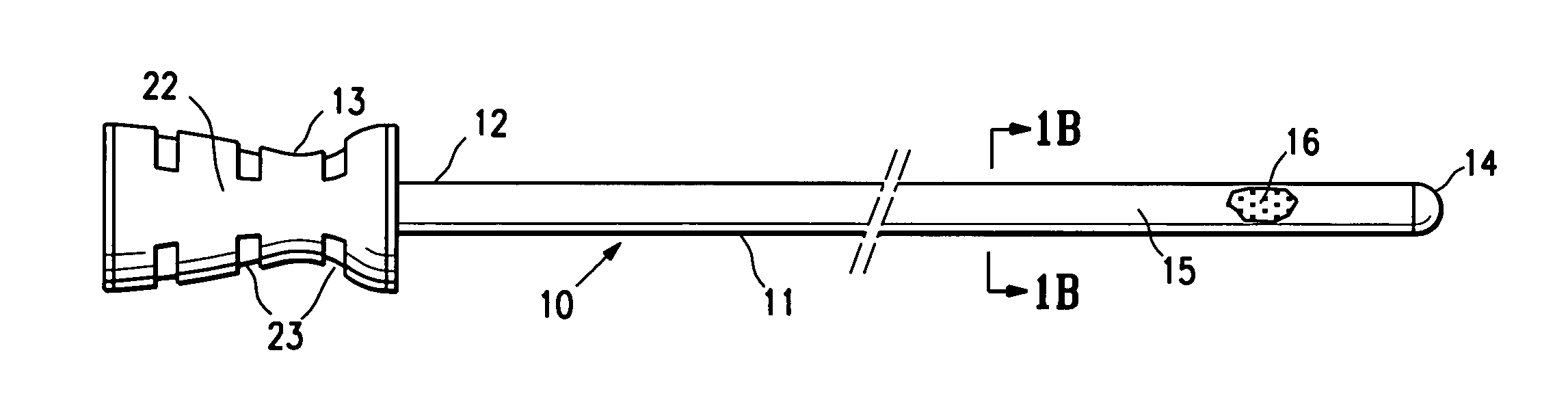
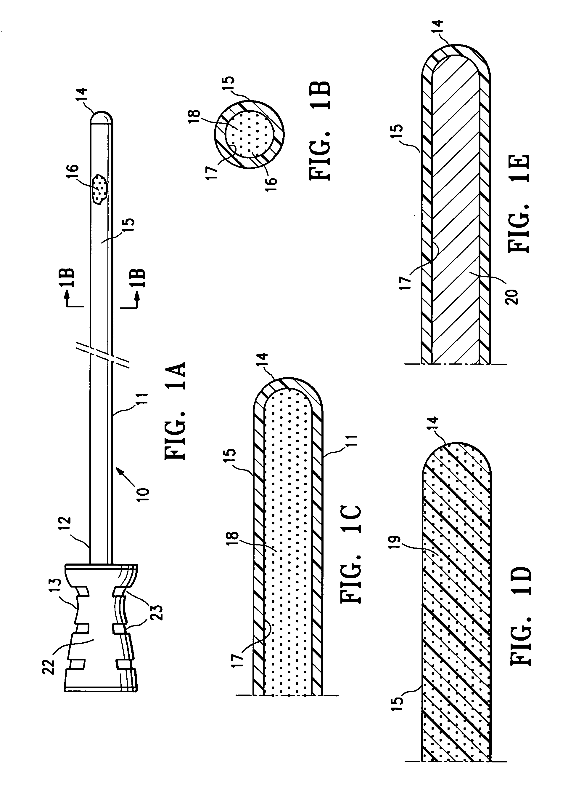
[0027]The present invention is directed to devices and methods for marking an intracorporeal site within a patient's body, and particularly to an obturator having an MRI detectable mass in the distal shaft portion thereof for marking the intracorporeal site.

[0028]FIGS. 1A-C illustrate an embodiment of an obturator 10 having an elongated shaft 11, a proximal end 12, a handle 13 on the proximal end, a closed distal end 14 and a distal shaft portion 15 with an MRI detectable mass 16. The MRI detectable mass may be in a solid, semi-solid, e.g. a gel or a slurry, or liquid state. Non-flowable gels are presently preferred. As shown in FIGS. 1B and 1C, the distal shaft portion 15 has an inner lumen 17 that is filled with a gel 18 having an MRI detectable material incorporated therein. An alternative embodiment is shown in FIG. 1D wherein the distal shaft portion 16 is solid 19 and has an MRI detectable material incorporated therein. FIG. 1E depicts yet another alternative embodiment in whi...


PUM


Abstract

An obturator with an elongated shaft, a proximal end, a substantially closed distal end and a MRI detectable distal shaft portion, which does not interfere with magnetic resonance imaging of tissue proximate thereto. Preferably, the distal shaft portion has an effective MRI detectable mass so as to provide a clear, T1-weighted image within an outline of the distal shaft portion upon magnetic resonance imaging.

Description

RELATED APPLICATIONS[0001]This application relates to and claims priority to application Ser. No. 11 / 978,782 filed Oct. 30, 2007; application Ser. No. ______ (Atty. Docket No. SENOP-06802), filed Oct. 30, 2007, provisional application Ser. No. 60 / 860,887, filed Nov. 24, 2006, and provisional application Ser. No. 60 / 872,020, filed Nov. 30, 2006, all of which are incorporated herein by reference.FIELD OF THE INVENTION[0002]This invention relates generally to the fields of medical treatment devices and methods. In particular, the invention relates to devices and methods for marking a body site, such as a site from which cancerous, pre-cancerous, or other tissue has been or will be removed.BACKGROUND OF THE INVENTION[0003]In diagnosing and treating certain medical conditions, it is often desirable to perform a biopsy, in which a specimen or sample of tissue is removed for pathological examination, tests and analysis. A biopsy typically results in a biopsy cavity occupying the space form...

Claims


Application Information

Patent Timeline
IPC IPC(8): A61B5/055A61B10/02
CPCA61B17/3417A61B17/3496A61B19/54A61B17/32A61B2019/5454A61B2019/5487A61B2019/5408A61B17/3431A61B17/3468A61B17/3498A61B2017/00477A61B2017/00911A61B2090/062A61B90/39A61B2090/3954A61B2090/3987A61B2090/3908
Inventor LUBOCK, PAULJONES, MICHAEL L.BROADAWAY, ETHANLOUW, FRANK R.
Owner SENORX
Why Eureka
Try Eureka