

Disk array system, disk array method, and computer product
- Summary
- Abstract
- Description
- Claims
- Application Information
AI Technical Summary
Benefits of technology
Problems solved by technology
Method used
Image

Examples
first embodiment
[0026]The disk array system includes a disk enclosure and a disk controller, the disk controller controls reading of data from or writing to a plurality of disk devices of the disk enclosure, and communication between the disk enclosure and the disk controller is made by using various SCSI commands, which makes it possible to construct an optimum system in a short time.
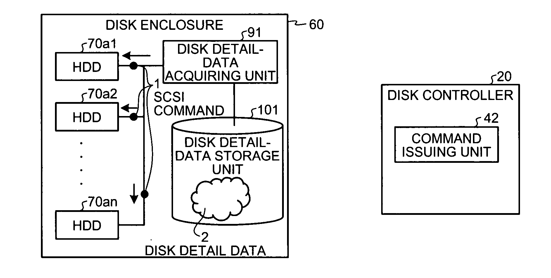
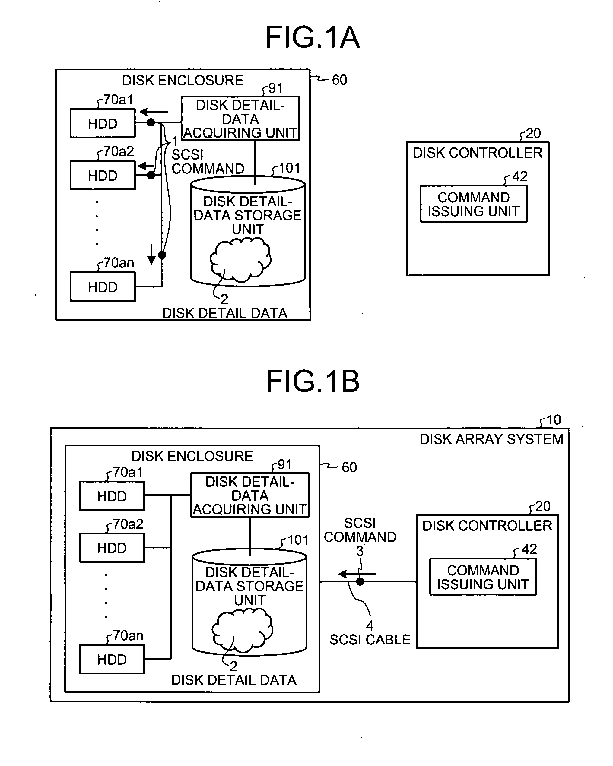
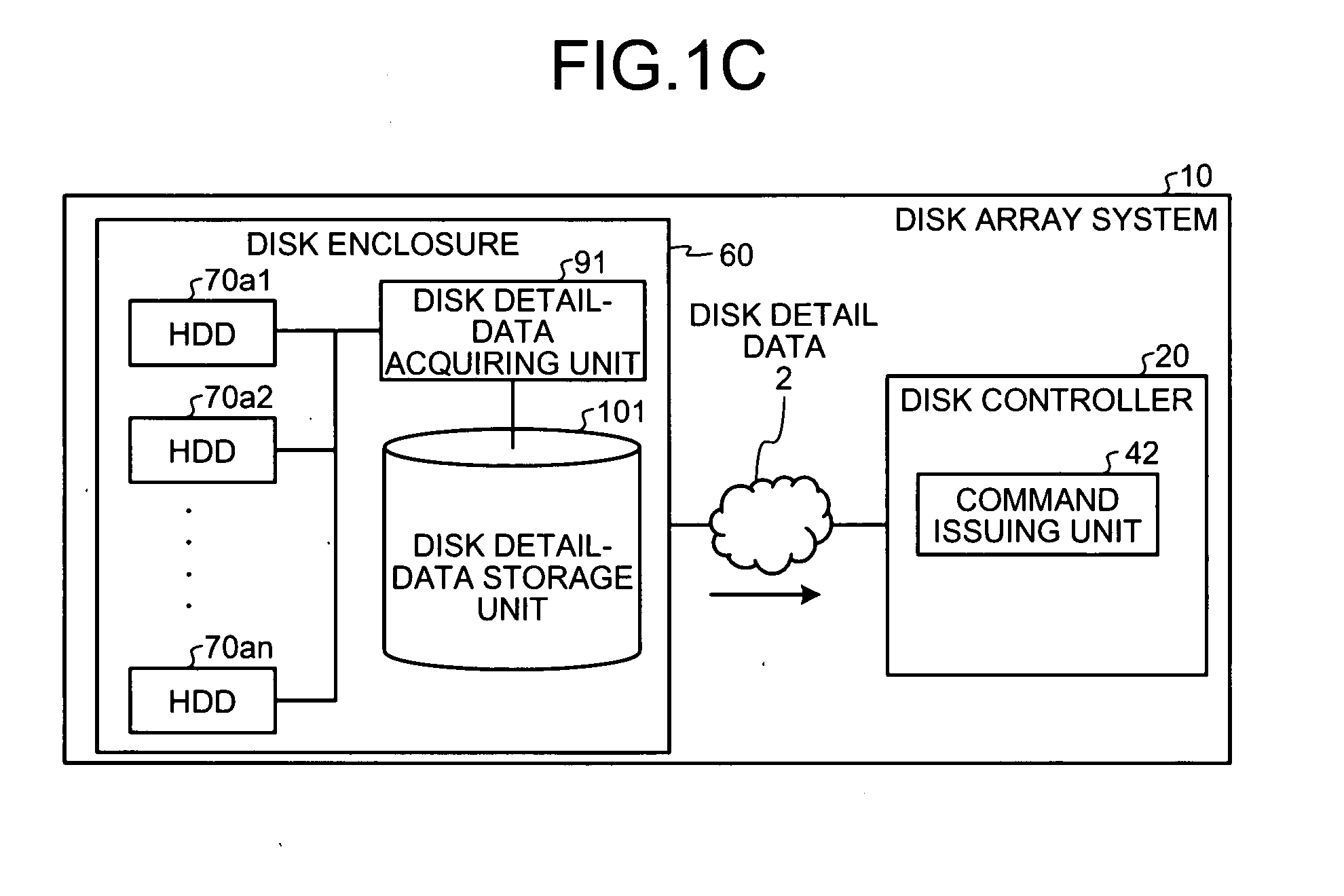
[0027]The features of the disk array system are explained in detail below. As shown in FIG. 1A, a disk array system 10 includes a disk enclosure 60 and a disk controller 20. The disk enclosure 60 issues an SCSI command to each of hard disk drives (HDDs) 70a1 to 70an, acquires disk detail data from each of the HDDs 70a1 to 70an, and stores therein the disk detail data. The HDDs 70a1 to 70an correspond to “plurality of disk devices” described in the claims.
[0028]To be specific, the disk enclosure 60 issues an SCSI command 1 such as an inquiry command or a send diagnostic command to the HDDs 70a1 to 70an by using a disk...
second embodiment
[0051]FIG. 5 is a functional block diagram of a disk array system 110 according to the The disk controller 20 and the disk enclosure 60 are connected to each other via the SCSI cable 4 and a local area network (LAN) cable 5 in the disk array system 110.
[0052]The disk controller 20 controls the disk array system 110 in such a manner that the disk array system 110 works as a storage device to or from which an external data processor can write or read data. The disk controller 20 includes a first communication control interface 120, a second communication control interface 130, the processor 40 that includes the HDD access processor 41 and the command issuing unit 42, and the storage unit 50 that stores therein data used for the various processes performed by the processor 40. Same numerals are assigned to units performing operations similar to those according to the first embodiment. The explanation for such units is not repeated, and only the HDD access processor 41, the first commu...
third embodiment
[0065]FIG. 6 is a functional block diagram of a disk array system 160 according to the As shown in FIG. 6, the disk array system 160 includes the disk controller 20 and the disk enclosure 60, both connected to each other via the SCSI cable 4 and the LAN cable 5.
[0066]The disk enclosure 60 stores the HDDs 70a1 to 70an, the first communication control interface 140, the second communication control interface 150, the processor 90 that includes a disk detail-data acquiring unit 93, a greatest-common support transfer rate calculating unit 94, a transfer rate setting unit 95, and a returning unit 96, and the storage unit 100 that includes the disk detail-data storage unit 101 and a greatest-common support transfer rate storage unit 102. Same numerals are assigned to units performing the operations similar to those according to the first and the second embodiments. The explanation for such units is not repeated, and the disk detail-data acquiring unit 93, the greatest-common support tran...
PUM
 Abstract
Description
Claims
Application Information