Leak detection in a fuel cell system

a fuel cell and leak detection technology, applied in the direction of fluid tightness measurement, instruments, electrochemical generators, etc., can solve problems such as showing the presence of leaks

Inactive Publication Date: 2008-06-19
GM GLOBAL TECH OPERATIONS LLC
View PDF3 Cites 39 Cited by
  • Summary
  • Abstract
  • Description
  • Claims
  • Application Information

AI Technical Summary

Problems solved by technology

Because the power output for a given amount of input fuel is known, when the power output drops relative to the fuel input it shows the presence of a leak.

Method used


Image

  • Leak detection in a fuel cell system
  • Leak detection in a fuel cell system
  • Leak detection in a fuel cell system

Examples


Embodiment Construction

[0015]The following detailed description and appended drawings describe and illustrate various exemplary embodiments of the invention. The description and drawings serve to enable one skilled in the art to make and use the invention, and are not intended to limit the scope of the invention in any manner. In respect of the methods disclosed, the steps presented are exemplary in nature, and thus, the order of the steps is not necessary or critical.

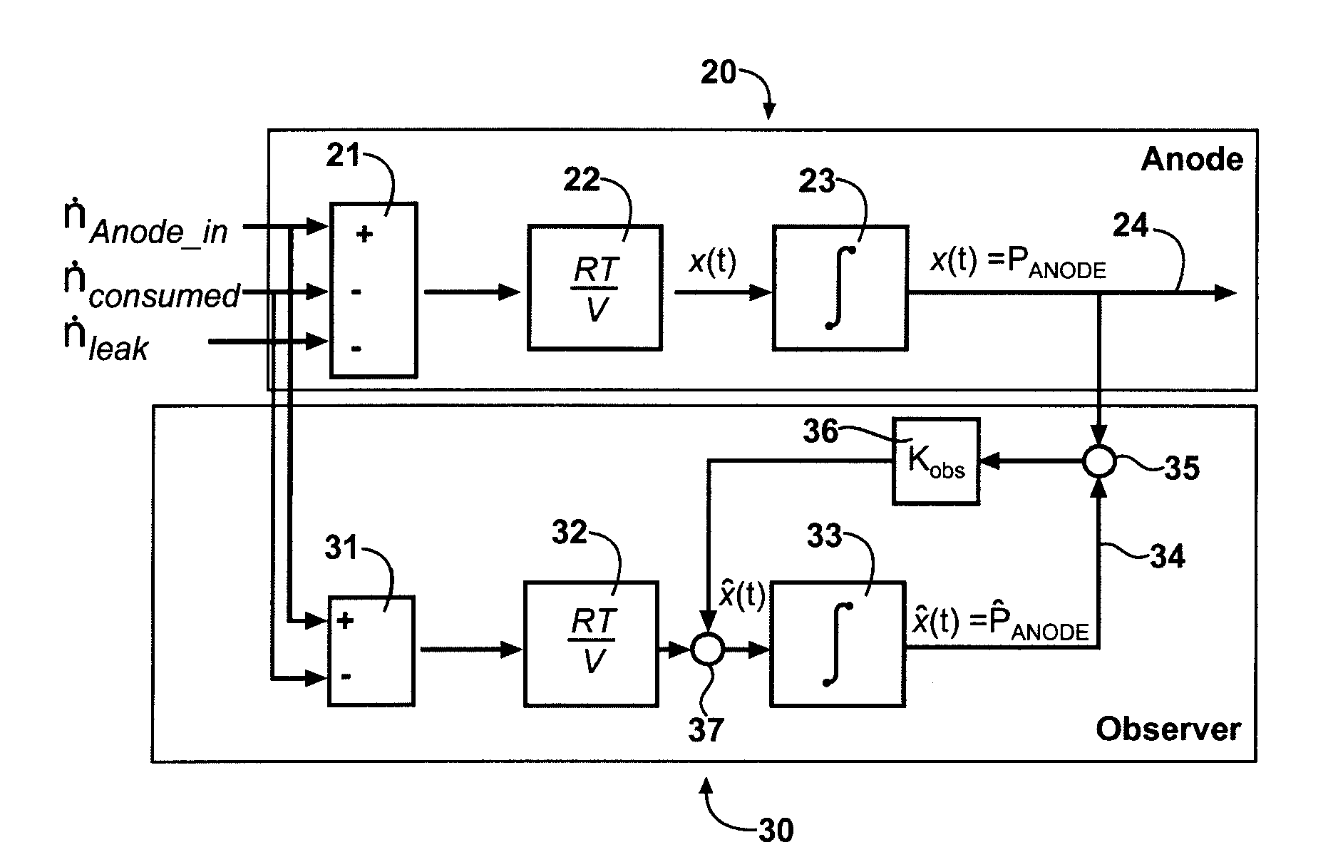
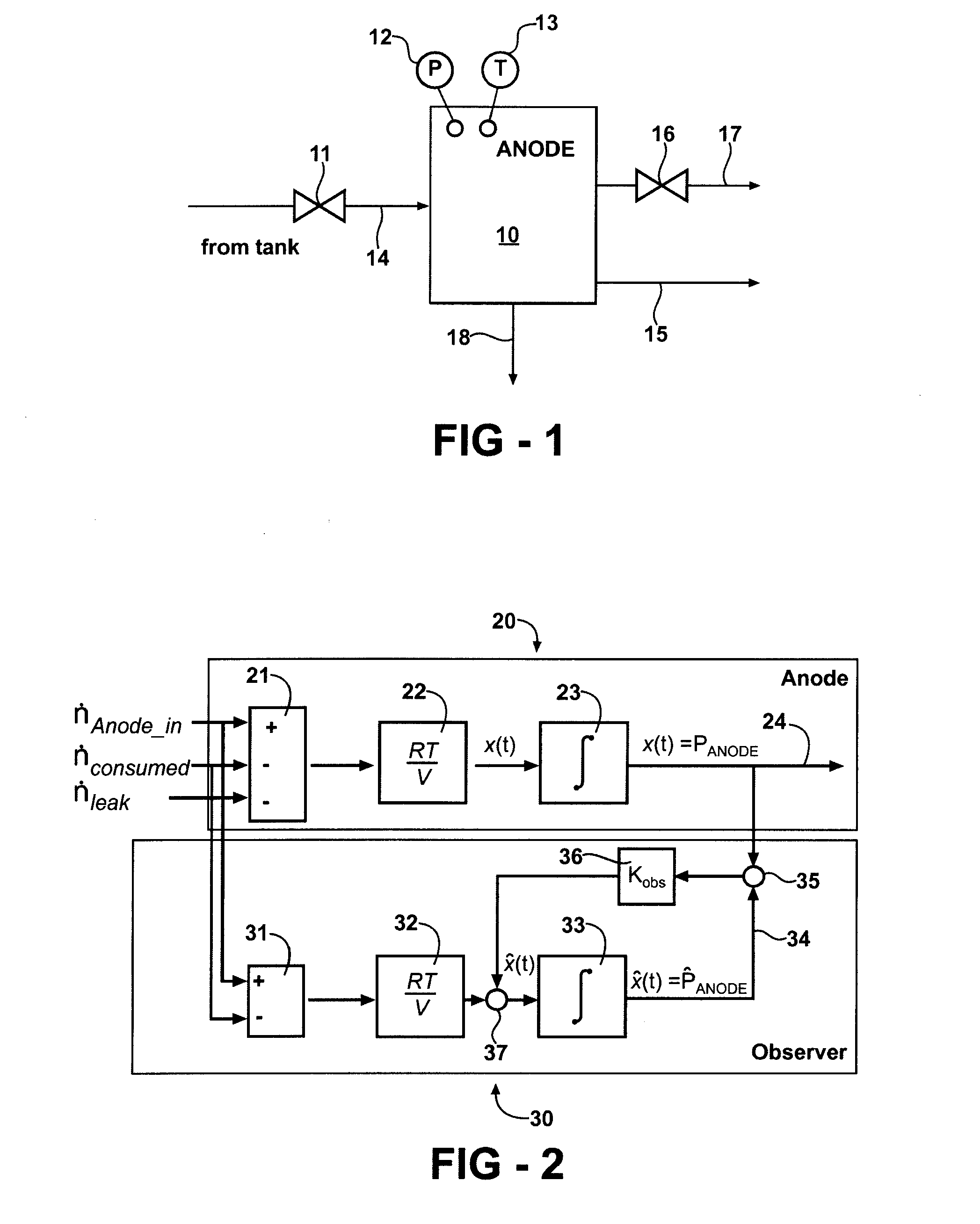
[0016]FIG. 1 is a schematic representation of a fuel cell anode 10 with an input and outputs. An input 14 is connected to a source (tank) of hydrogen through an input valve or injector 11. The outputs include an anode pressure signal 12 and an anode temperature signal 13. The rate of hydrogen moles converted in the fuel cell stack (output 18) is proportional to the stack current. Under stable conditions, the conversion rate is equal to the input rate plus a small amount of hydrogen crossover to the cathode. During stack operation, nitrogen a...


PUM


Abstract

A diagnostic method of detecting component failures in a fuel cell anode subsystem involves estimating fuel flow through injectors and comparing the estimated flow with a model based upon the system parameters. An observer based model is used to determine a residual value, the difference between the hydrogen input and the hydrogen consumed, and the residual is compared with a threshold range. In alternative embodiments, the stack current and the state of the valves are used to calculate the required hydrogen flow through the injectors and the duty cycle of an injector is compared to a tolerance range.

Description

FIELD OF THE INVENTION[0001]This invention relates to a method of detecting hydrogen leaks in the anode of a fuel cell system.BACKGROUND OF THE INVENTION[0002]Electrochemical fuel cells convert fuel and an oxidant into electricity, a reaction product (such as water in the case of a hydrogen fueled and oxygen oxidizing fuel cell) and heat. In a hydrogen fueled and oxygen oxidizing fuel cell, the hydrogen enters the anode and the oxygen enters the cathode.[0003]In the case of fuel cells for portable applications where air is available, such as automobiles, it can be easier to provide the oxygen for the reaction by using this air. This eliminates the need to carry oxygen in addition to hydrogen or some source of hydrogen. But there is a cost for using air instead of pure oxygen. Air contains many gasses other than oxygen. Nitrogen is the most common gas in the atmosphere comprising approximately three-fourths of air. Some nitrogen will eventually find its way from the cathode to the an...

Claims


Application Information

Patent Timeline
Patent Type & Authority Applications(United States)
IPC IPC(8): G01M3/26
CPCG01M3/3254H01M8/04007H01M8/04089H01M8/04305H01M8/0432Y02T90/32H01M8/04589H01M8/04679H01M2250/20Y02E60/50H01M8/04388Y02T90/40
Inventor SIENKOWSKI, JON R.ARTHUR, DAVID A.ALP, ABDULLAH B.GADE, PRASADWEISPFENNING, THOMASWILLIMOWSKI, PETERTHYROFF, JURGEN
Owner GM GLOBAL TECH OPERATIONS LLC
Why Eureka
Try Eureka