Step for temporary installation

Inactive Publication Date: 2008-06-19
WORLD WAY SAFETY S R O
View PDF29 Cites 2 Cited by
  • Summary
  • Abstract
  • Description
  • Claims
  • Application Information

AI Technical Summary

Benefits of technology

[0005]An embodiment with pin joints outside of the lateral sides of the board is preferable to improve the stability of the stairs.
[0006]It is preferable to have a rail consisting of a bottom side provided with pins for piercing into the soil and a higher upper batten carrying the pin joint and being provided with holes with which the bottom part of t

Problems solved by technology

The disadvantage of both described stairs resides in that they are unable to match the changeable surface of the slope, which results in moving under the user longitudinally and transversally and making climbing

Method used


Image

  • Step for temporary installation
  • Step for temporary installation

Examples


Embodiment Construction

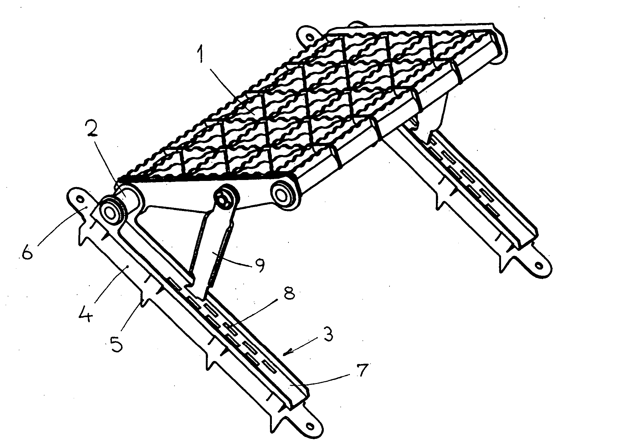
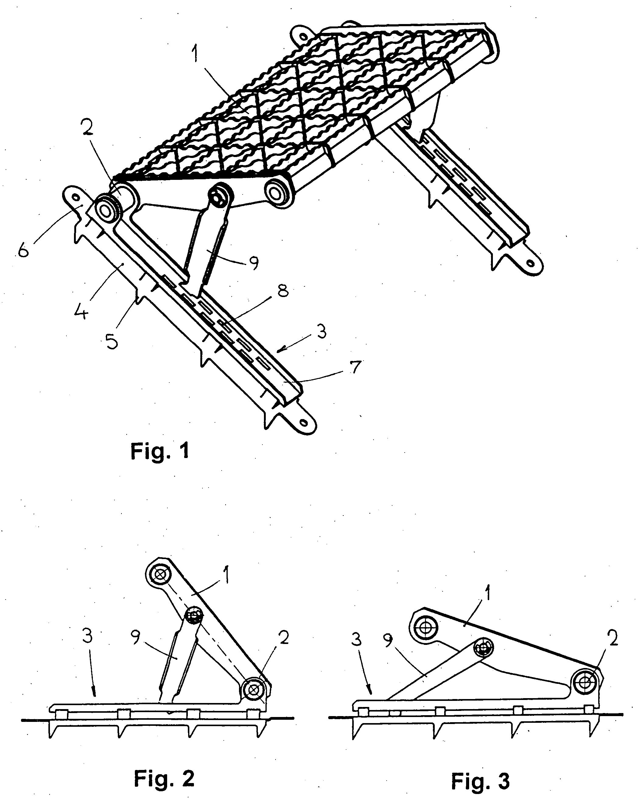
[0012]The step for temporary installation upon slopes consists of a step board 1 executed as a grid and provided laterally with pin joints 2 with horizontal axis at its rear side. Rails 3 consisting of two parts are pivoted to board 1 by way of pin joints 2 located outside of the step board 1. The bottom part 4 in form of U profile is provided with pins 5 at the bottom side for being driven into the ground and bears projections 6 with holes that serve for linking of adjacent steps, e.g. by nails driven into the ground. The elevated upper batten 7 bears a pin joint 2 and has two rows of offset holes 8. These holes serve for accepting the bottom end of strut 9 pivoted by its upper end at the side of step board 1.

[0013]The step can be installed upon a slope by driving the pins 5 of rails 3 into the ground, whereupon the bottom ends of struts 9 are inserted into holes 8 so as to ensure the horizontal position of board 1. It is obvious that this arrangement will enable, by suitable choic...


PUM


Abstract

A step for temporary installation upon slopes, comprising a step board (1) pivoting around its horizontal axis and provided with tilting struts (9) for adjusting the angle between the plane of the board and the plane of the slope, bears at its rear side lateral pin joints (2) attaching rails (3) whose bottom side is provided with means for fixing to the slope.

Description

TECHNICAL FIELD[0001]The invention relates to a step for temporary installation upon a slope, consisting of a step board pivoting around its horizontal axis and provided with tilting struts for adjusting the angle between the plane of the board and the plane of the slope.PRIOR ART[0002]When working on steep slopes, such as during rescue work in water channels, during construction and maintenance work on roofs etc., various devices are used for ensuring relatively comfortable and safe temporary stairs. The specification CH 636166 discloses a ladder intended for working upon slopes and provided with stair steps pivoting in lengthwise profiles. Each board accommodates a toothed wheel inside the profile, all wheels being interlinked by way of a rack bar serving to adjust the same position, i.e. horizontal position of all steps on any slope, by moving the rack bar. The abstract JP 9268868 describes a temporary step consisting of a H-shaped frame made of tubes supporting the pivoting step...

Claims


Application Information

Patent Timeline
IPC IPC(8): E04G21/32E04G1/15
CPCE04G3/26E04D15/02E04G3/265
Inventor JOST, PETR
Owner WORLD WAY SAFETY S R O
Why Eureka
Try Eureka