
Attenuator and step attenuation device having the same

Inactive Publication Date: 2008-06-19
DIALOG SEMICON KOREA INC
View PDF1 Cites 0 Cited by
  • Summary
  • Abstract
  • Description
  • Claims
  • Application Information

AI Technical Summary

Benefits of technology

[0006]The present invention provides an attenuator having high attenuation accuracy and low insertion loss with respect to an input signal.
[0007]The present invention also provides a step attenuation device having high attenuation accuracy and low insertion loss with respect to an input signal.

Problems solved by technology

However, when the T-type attenuator has a large attenuation amount, the accuracy deteriorates.
However, the insertion loss is large with respect to the signal path.

Method used


Image

  • Attenuator and step attenuation device having the same
  • Attenuator and step attenuation device having the same
  • Attenuator and step attenuation device having the same

Examples


Embodiment Construction

[0022]Hereinafter, exemplary embodiments of the present invention will be described in detail with reference to the attached drawings.

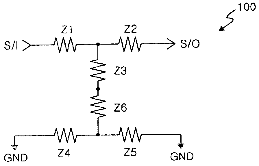
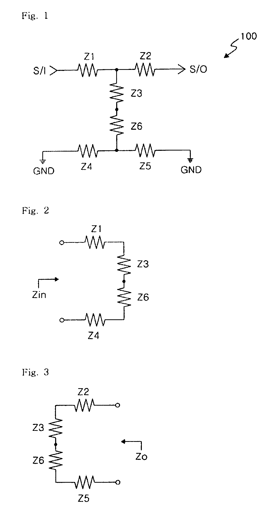
[0023]FIG. 1 illustrates an attenuator according to an embodiment of the present invention.

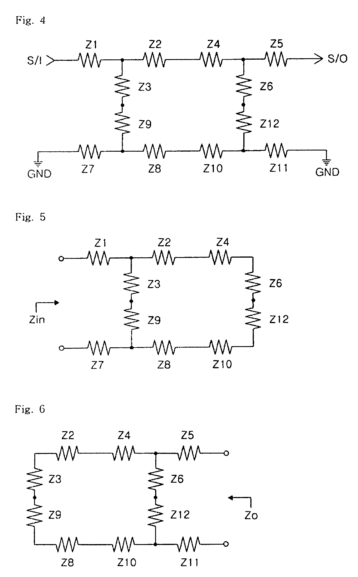
[0024]Referring to FIG. 1, an attenuator 100 according to the embodiment includes impedance components Z1 to Z6.

[0025]Since two basic T-type attenuators are connected to each other in a mirror configuration in the attenuator 100 shown in FIG. 1, the attenuator 100 is referred to as a mirror T-type attenuator.

[0026]A basic T-type attenuator is constructed with serially connected first and second impedance components Z1 and Z2 and a third impedance component Z3 connected to the common terminal of the first and second impedance components Z1 and Z2.

[0027]The other basic T-type attenuator is constructed with serially connected fourth and fifth impedance components Z4 and Z5 and a sixth impedance component Z6 connected to the common terminal of the fourth and fifth i...


PUM


Abstract

An attenuator for attenuating an input signal at a predetermined rate and a step attenuation device having the same are provided. The attenuator includes first to sixth impedance components. A terminal of the first impedance component is connected to an input signal. A terminal of the second impedance component is connected to the other terminal of the first impedance component. The other terminal of the second impedance component outputs an attenuated signal. A terminal of the third impedance component is connected to a common terminal of the first and second impedance components. A terminal of the fourth impedance component is connected to a ground voltage. A terminal of the fifth impedance component is connected to the other terminal of the fourth impedance component. The other terminal of the fifth impedance component is connected to the ground voltage. A terminal of the sixth impedance component is connected to a common terminal of the fourth and fifth impedance component. The other terminal of the sixth impedance component is connected to the other terminal of the third impedance component.

Description

BACKGROUND OF THE INVENTION[0001]1. Field of the Invention[0002]The present invention relates to an attenuator and a step attenuation device having the same, and more particularly, to an attenuator capable of improving attenuation accuracy and reducing insertion loss with respect to an input signal and a step attenuation device having the same.[0003]2. Description of the Related Art[0004]An attenuator serves to generate an attenuated signal by attenuating an input signal at a predetermined rate. The attenuator is applied to various fields of radio frequency (RF) electronics. In general, the attenuator is used to decrease a power level to a desirable level. In addition, the attenuator is widely used to decrease oscillation or to reduce reflection loss.[0005]Resistance elements of a conventional attenuator construct a T-type or Π-type structure. In case of the T-type attenuator, the insertion loss is small with respect to a signal path. However, when the T-type attenuator has a large ...

Claims


Application Information

Patent Timeline
IPC IPC(8): H01P1/22
CPCH03H7/24H01P1/22
Inventor HONG, SEOK YONGHWANG, MYUNG WOON
Owner DIALOG SEMICON KOREA INC
Learn More