Antenna for a backscatter-based RFID transponder

a backscatter-based rfid and antenna technology, applied in the direction of resonant antennas, instruments, burglar alarm mechanical actuation, etc., can solve the problems of reducing the range, reducing the cost of transponder implementation, and reducing the range of the antenna, so as to achieve wide-band reception, simple and inexpensive implementation, and simple

Active Publication Date: 2008-06-19
ATMEL CORP
View PDF6 Cites 16 Cited by
  • Summary
  • Abstract
  • Description
  • Claims
  • Application Information

AI Technical Summary

Benefits of technology

[0019]It is therefore an object of the present invention to provide an antenna for a backscatter-based RFID transponder with an integrated receive circuit (IC) for receiving a radio signal spectrally located in an operating frequency range, that permits simpler and more economical implementations while still permitting very wide-band reception of high-frequency radio signals as well as having directional characteristics that are as omnidirectional as possible. It is a further object of the invention to provide a backscatter-based RFID transponder that is simple and inexpensive to implement and that has a relatively long range with very wide-band, omnidirectional reception of high-frequency radio signals.
[0022]In an embodiment, two U-shaped trace segments are placed parallel or substantially parallel to one another and are connected to one another (contacting) in each of the two antenna branches. This makes possible antennas and transponders that require only a very small, e.g. elongated, area and that can be implemented in a simpler and more economical manner. At the same time, such an antenna permits greater ranges while still allowing very wide-band and largely omnidirectional reception of high-frequency radio signals.
[0024]In another embodiment, the second and third trace segments can each be piecewise linear in design. In this way, better area utilization by the antenna can be achieved for a given rectangular or square area.
[0025]In another embodiment, the first trace segment is designed so that the antenna can have an inductive impedance in the operating frequency range that approximates the complex conjugate values of the capacitive impedance in such a manner that no circuit arrangement is needed for impedance matching between the antenna and integrated receive circuit. The first trace segment 24 can be designed such that the antenna has an inductive impedance in the operating frequency range whose real component is below 35 ohms and whose imaginary component has a magnitude above 170 ohms. This results in particularly long ranges as well as transponders that are particularly simple to implement.
[0026]Each antenna branch can have a serpentine fourth trace segment that is designed to connect the connecting region to the second trace segment of the antenna branch. In this way, it is advantageously possible to reduce the overall length of the area occupied by the antenna. Preferably, the fourth trace segments in this context have a third trace width that is smaller than a first trace width of a second or third trace segment. By this means, small effective resistances of the antenna impedance can advantageously be achieved.
[0027]In an embodiment of the inventive RFID transponder, the integrated receive circuit is arranged in the connecting region of the antenna. This permits very simple implementations of the transponder.

Problems solved by technology

A disadvantage here is that the impedance of this antenna differs sharply from the complex conjugate value of the impedance of the chip input circuit, and thus that an additional, separate matching circuit with a coil and a capacitor is required.
Because of parasitic resistances of these components, power losses arise in the transponder, disadvantageously reducing the range.
Moreover, the separate matching circuit restricts the freedom in placement of the chip and results in more complex and thus more expensive implementations of the transponder.
However, for many applications only a relatively small area is available.

Method used


Image

  • Antenna for a backscatter-based RFID transponder
  • Antenna for a backscatter-based RFID transponder
  • Antenna for a backscatter-based RFID transponder

Examples


Embodiment Construction

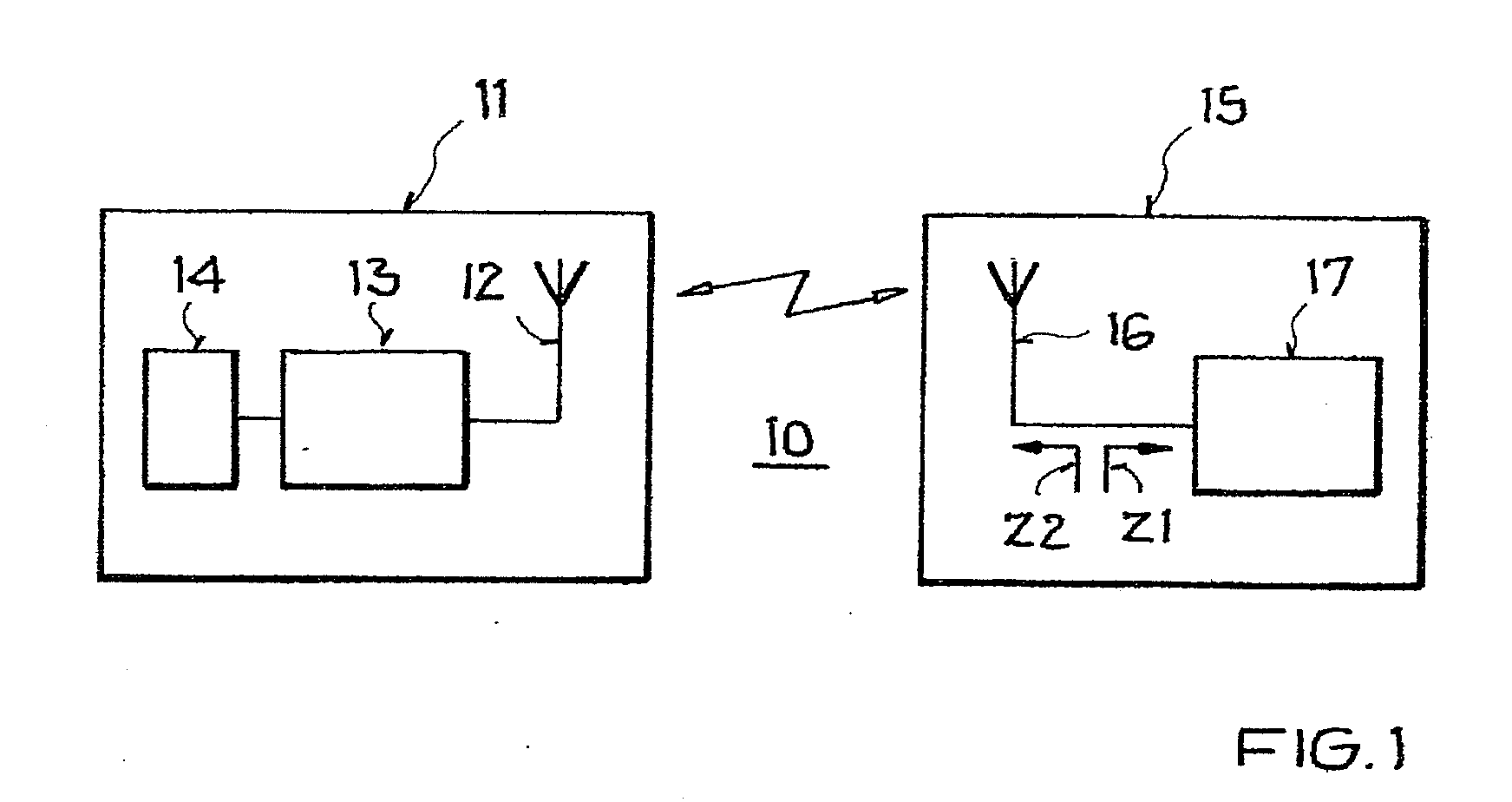
[0034]FIG. 1 schematically shows an example of an RFID system. The RFID system 10 has a base station 11 and at least one inventive transponder 15. By means of high-frequency radio signals, the base station 11 exchanges data with the transponder or transponders 15 in a contactless and bidirectional fashion.

[0035]The base station 11 has at least one antenna 12 for transmitting and receiving radio signals in an operating frequency range fB, a transmitting / receiving unit 13 connected to the antenna(s) for transmitting and receiving data, and a control unit 14 connected to the transmitting / receiving unit for controlling the transmitting / receiving unit 13.

[0036]The backscatter-based passive or semi-passive transponder 15 has an antenna 16 for receiving the radio signal spectrally located in the operating frequency range fB, and has, connected to the antenna, a receive circuit 17 for demodulating the received radio signal and for detecting the data contained therein. The receive circuit 17...


PUM


Abstract

An antenna for a backscatter-based RFID transponder is provided that has an integrated receive circuit having a capacitive input impedance for receiving a radio signal spectrally located in an operating frequency range. The antenna includes two antenna branches that extend outward from a connecting region in which the antenna branches can be connected to the integrated receive circuit, and a yoke-shaped first trace segment that is designed to connect the two antenna branches together. Each antenna branch can have a U-shaped second trace segment connected to the connecting region, and a U-shaped third trace segment connected to the second trace segment and extending parallel to the second trace segment. The invention further relates to a backscatter-based RFID transponder with such an antenna.

Description

[0001]This nonprovisional application claims priority to German Patent Application No. DE 102006055744, which was filed in Germany on Nov. 25, 2006, and to U.S. Provisional Application No. 60 / 860,792, which was filed on Nov. 24, 2006, and which are both herein incorporated by reference.BACKGROUND OF THE INVENTION[0002]1. Field of the Invention[0003]The present invention relates to an antenna for a backscatter-based RFID (radio frequency identification) transponder, and a backscatter-based RFID transponder having such an antenna.[0004]2. Description of the Background Art[0005]The invention resides in the field of wireless and contactless communication. It resides particularly in the field of radio-based communication for the purpose of identifying objects, animals, persons, etc., as well as the transponders and remote sensors used for this purpose.[0006]While applicable in principle to any desired contactless communication system, the present invention and the problem on which it is ...

Claims


Application Information

Patent Timeline
Patent Type & Authority Applications(United States)
IPC IPC(8): G08B13/14
CPCH01Q1/2225H01Q9/065H01Q1/36
Inventor FISCHER, MARTIN
Owner ATMEL CORP
Why Eureka
Try Eureka