Receiving apparatus

a technology of receiving apparatus and receiver, which is applied in the direction of selective content distribution, television system, color signal processing circuit, etc., can solve the problems of difficult ic of the tuner portion, difficult to ensure a high degree of image suppression exceeding 30 db, and increase the scale of the circuit, etc., to achieve excellent image rejection performance, wide-band reception, and high degree of selection

Inactive Publication Date: 2006-08-29
PANASONIC CORP
View PDF14 Cites 34 Cited by
  • Summary
  • Abstract
  • Description
  • Claims
  • Application Information

AI Technical Summary

Benefits of technology

[0032]The present invention was developed in light of conventional problematic points and an object of the present invention is to provide a receiving apparatus which has a high degree of selection with excellent image rejection performance while realizing wide-band reception from VHF to UHF.

Problems solved by technology

Since disturbance occurs in such frequency conversion, frequency components at unnecessary sides must be removed by a filer prior to the frequency conversion.
Thus, it is usually difficult to ensure a high degree of image suppression exceeding 30 dB.
At this time, since resonance circuits corresponding to the number of bands are required, a scale of the circuit is increased and thus the IC of the tuner portion is difficult.
When a quadrature signal is generated not by a divider but by a phase shifter, it is difficult to ensure quadrature precision at a wide-band.
At this time, if the power of the interfering signal is relatively large, suppression cannot be performed thoroughly.
At this time, if the power of interfering signal is relatively large, suppression cannot be performed thoroughly.
Nevertheless, there arise problems in that a gain difference between an I axis and a Q axis is easily generated by such operation and thus an image rejection performance cannot be sufficiently obtained.
There also arises a problem in that an image rejection performance is deteriorated by switching of the phase shifters or an amount of the phase shift.

Method used


Image

  • Receiving apparatus
  • Receiving apparatus
  • Receiving apparatus

Examples


embodiment 1

[0078]FIG. 7 is a block diagram of a receiving apparatus 60 according to Embodiment 1 of the present invention. The receiving apparatus 60 is a receiving apparatus which performs partial reception, i.e., receives one segment. The receiving apparatus 60 is configured so as to include an antenna 61, an RF amplifier 62, a mixer 63, a PLL 64, a BPF 65, an IF amplifier 66, mixers 67 and 68, a PLL 69, a phase shifter 70, low pass filters (LPF) 71 and 72, phase shifters 73 and 74, an adder 75, a band pass filter (BPF) 76, a base band amplifier (BB amplifier) 77, an LPF 78, an AD converter (ADC) 79, an OFDM demodulator 80, a transport stream output terminal (TS output terminal) 81 and a control section 82.

[0079]The RF amplifier 62 is an amplifier which amplifies an RF signal including an ISDB-T signal received by the antenna 61. The mixer 63 is a circuit for converting a frequency into a first intermediate frequency fIF1 using an oscillation signal (local oscillator frequency fLO1) outputte...

embodiment 2

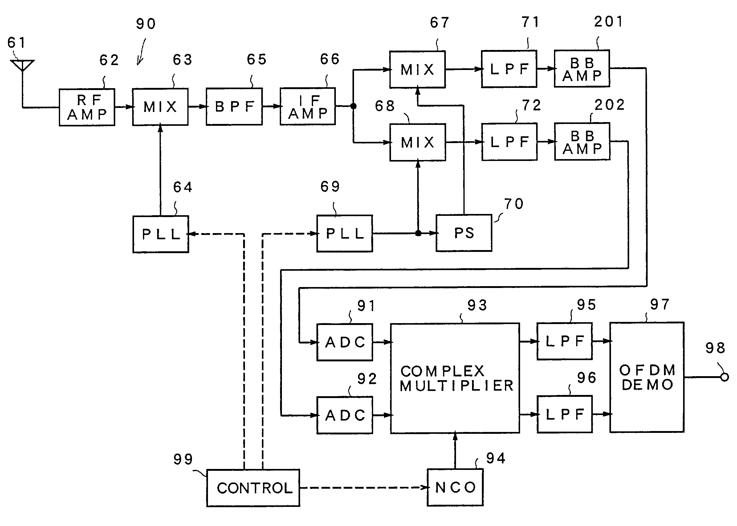
[0108]A receiving apparatus according to Embodiment 2 of the present invention will be described. FIG. 12 is a block diagram showing a structure of a receiving apparatus 90 of this embodiment. The same portions as those of the receiving apparatus 60 of Embodiment 1 shown in FIG. 7 are indicated by the same reference numerals and a detailed description thereof will not be repeated. The receiving apparatus 90 is configured so as to include an antenna 61, an RF amplifier 62, a mixer 63, a PLL 64, a BPF 65, an IF amplifier 66, mixers 67, 68, a PLL 69, a phase shifter 70, low pass filters (LPF) 71, 72, base band amplifiers (BB amplifiers) 201, 202, AD converters (ADC) 91, 92, a complex multiplier 93, a numerical control oscillator (NCO) 94, digital LPF 95, 96, an OFDM demodulator 97, a transport stream output terminal (TS output terminal) 98 and a control section 99.

[0109]The ADC 91 is a circuit for converting an analog I signal outputted from the BB amplifier 201 into a digital signal. ...

embodiment 3

[0146]Next, a receiving apparatus 60D according to Embodiment 3 of the present invention will be described. In accordance with this embodiment, two series of receiving apparatuses of Embodiment 1 are arranged in parallel in order to improve fading durability at a time of mobile reception and a space diversity receiver is formed. In this case, two series of OFDM demodulators 80 shown in FIG. 7 are prepared and a selection or weighted composition is performed for each carrier at FFT outputs of the receiving apparatuses, so that 2 series of received signals are integrated.

[0147]FIG. 18 is a configuration view showing a tuner portion of the receiving apparatus 60D of this embodiment. In accordance with the tuner portion of the receiving apparatus 60D, a first tuner portion and a second tuner portion are provided in parallel. The first tuner portion is configured so as to include an antenna 61a, an RF amplifier 62a, a mixer 63a, a PLL 64, a BPF 65a, an IF amplifier 66a, mixers 67a, 68a, ...


PUM


Abstract

Frequency conversion into a first intermediate frequency which is higher than a received frequency band is performed for a received signal by using a mixer and a PLL. Next, an output of the mixer is frequency converted into a second intermediate frequency of a base band by using a quadrature mixer formed by mixers and a phase shifter. At this time, a frequency of the local oscillation signal of a PLL supplied to the quadrature mixer is controlled so as to be switched, depending on a position of the received segment, between a frequency which is higher than the first intermediate frequency and a frequency which is lower than the same.

Description

BACKGROUND OF THE INVENTION[0001]1. Field of the Invention[0002]The present invention relates to a receiving apparatus in digital terrestrial broadcasting.[0003]2. Description of the Related Art[0004]A receiving apparatus disclosed in Japanese Unexamined Patent Publication No. 2001-77648 has been known as a conventional one. Hereinafter, prior art relating to the present invention will be described with reference to the drawings.[0005]FIG. 1 is a configuration view of a receiving apparatus according to a first conventional example. The receiving apparatus includes an antenna 1, an RF amplifier 2, mixers 7, 8, a PLL 9, a divider 10, low pass filters (LPF) 11, 12, phase shifters 13, 14, an adder 15, a band pass filter (BPF) 16, a base band amplifier (BB amplifier) 17, an LPF 18, an AD converter (ADC) 19, an OFDM demodulator 20 and a transport stream output terminal (TS output terminal) 21.[0006]An ISDB-T signal is inputted to the antenna 1. ISDB-T is a standard for digital terrestrial...

Claims


Application Information

Patent Timeline
Patent Type & Authority Patents(United States)
IPC IPC(8): H04N5/455H03D7/16H03J1/00H04B1/10H04N5/44
CPCH03D7/165H03J1/005H04N5/4401H04B1/1027H04N5/455H04N21/426
Inventor KANNO, IPPEIOZEKI, HIROAKIOBA, YASUOFUJISHIMA, AKIRAIWAIDA, MINEYUKI
Owner PANASONIC CORP
Why Eureka
Try Eureka