Automobile steering wheel and brake pedal locking device

Inactive Publication Date: 2008-06-26
DAVIS ROSS
View PDF24 Cites 6 Cited by
  • Summary
  • Abstract
  • Description
  • Claims
  • Application Information

AI Technical Summary

Benefits of technology

[0005]It is therefore an object of the present invention to provide a vehicle anti-theft device which me

Problems solved by technology

While these devices fulfill their respective objectives and requirements, these prior art devices all suff

Method used


Image

  • Automobile steering wheel and brake pedal locking device
  • Automobile steering wheel and brake pedal locking device
  • Automobile steering wheel and brake pedal locking device

Examples


Embodiment Construction

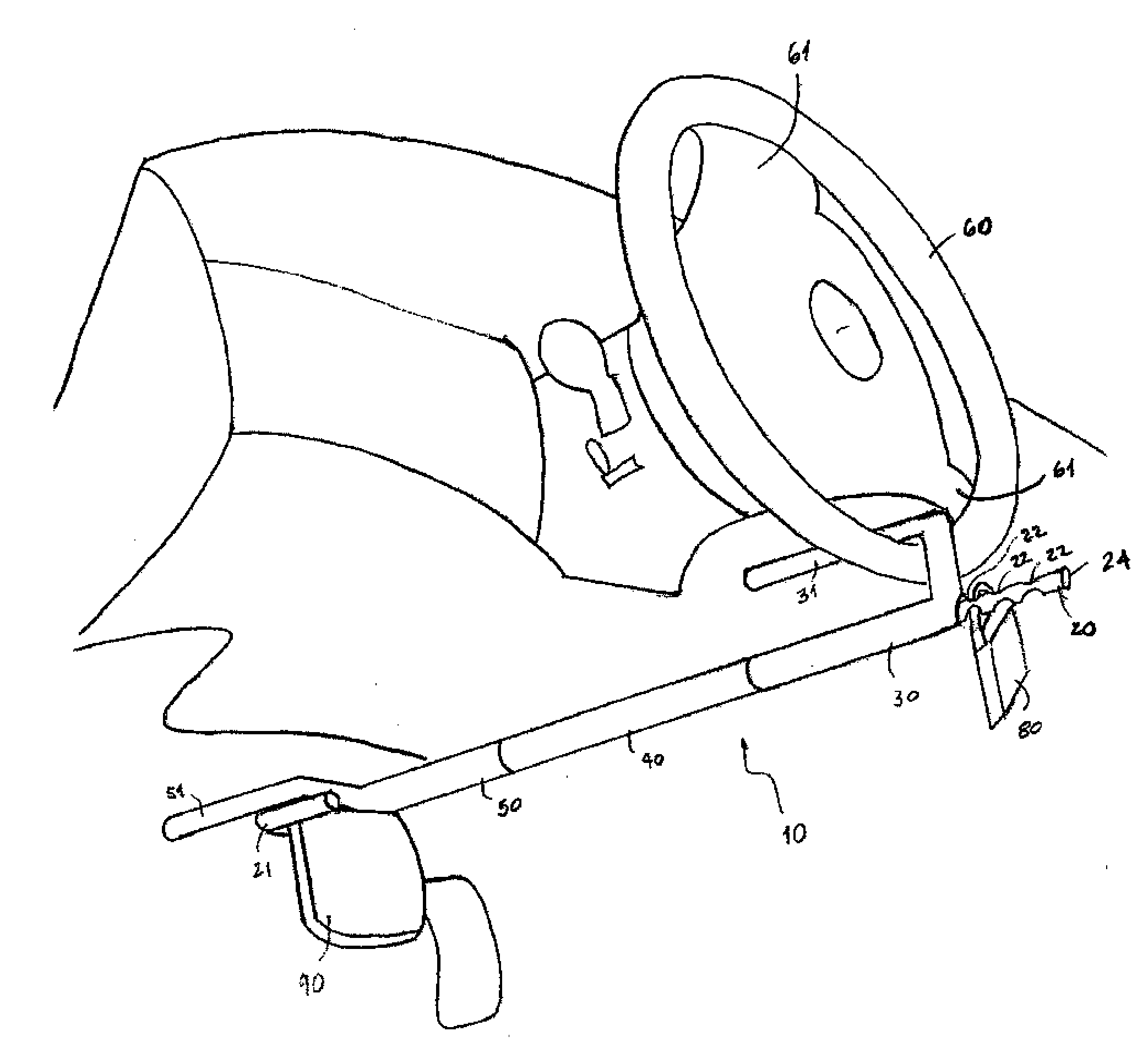
[0016]Referring to FIG. 1, an anti-theft device 10 is shown according to one embodiment of the present invention. As will be described below, anti-theft device 10 may be used to hook and immobilize the steering wheel and brake pedal of a vehicle to prevent theft.

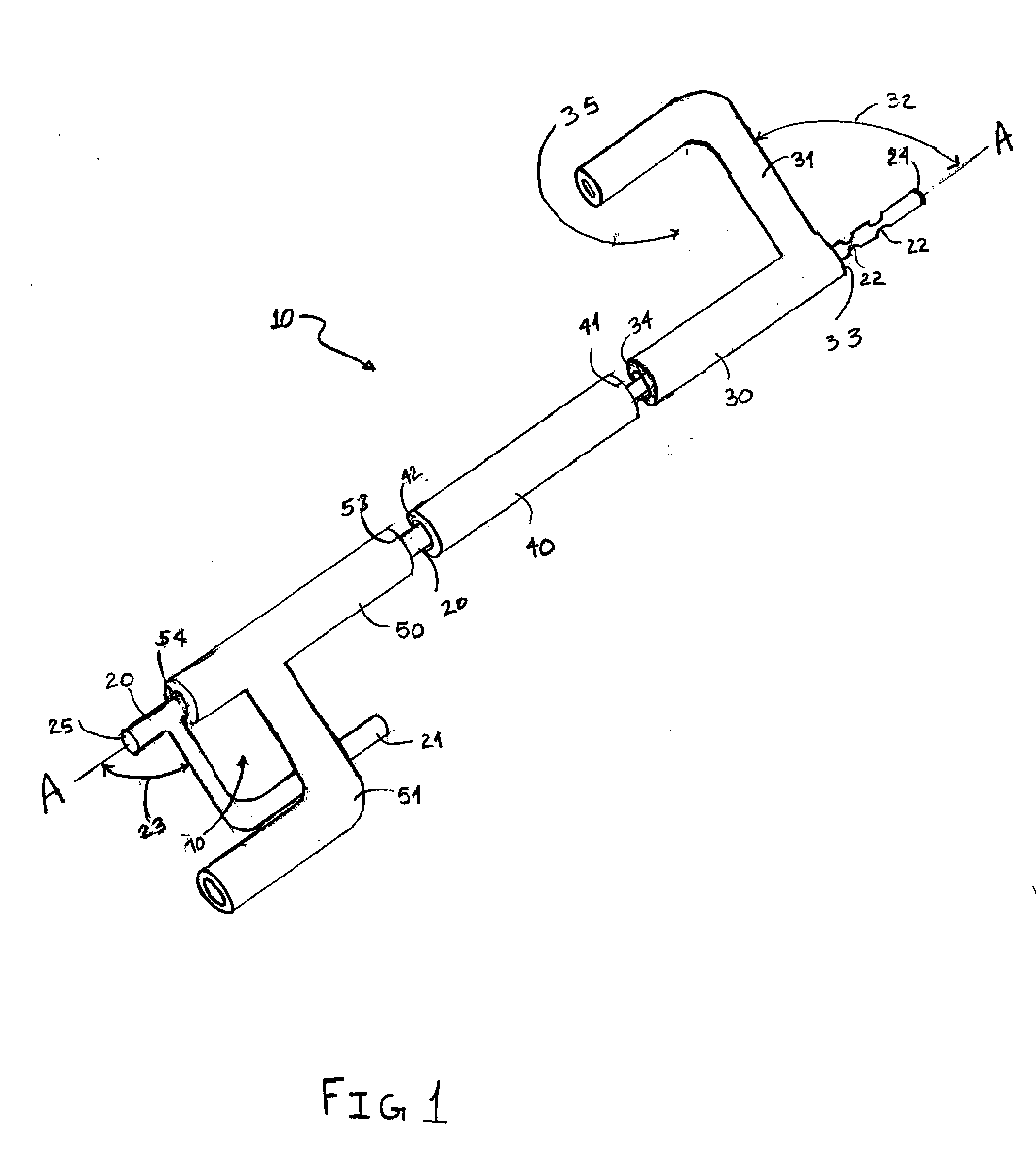
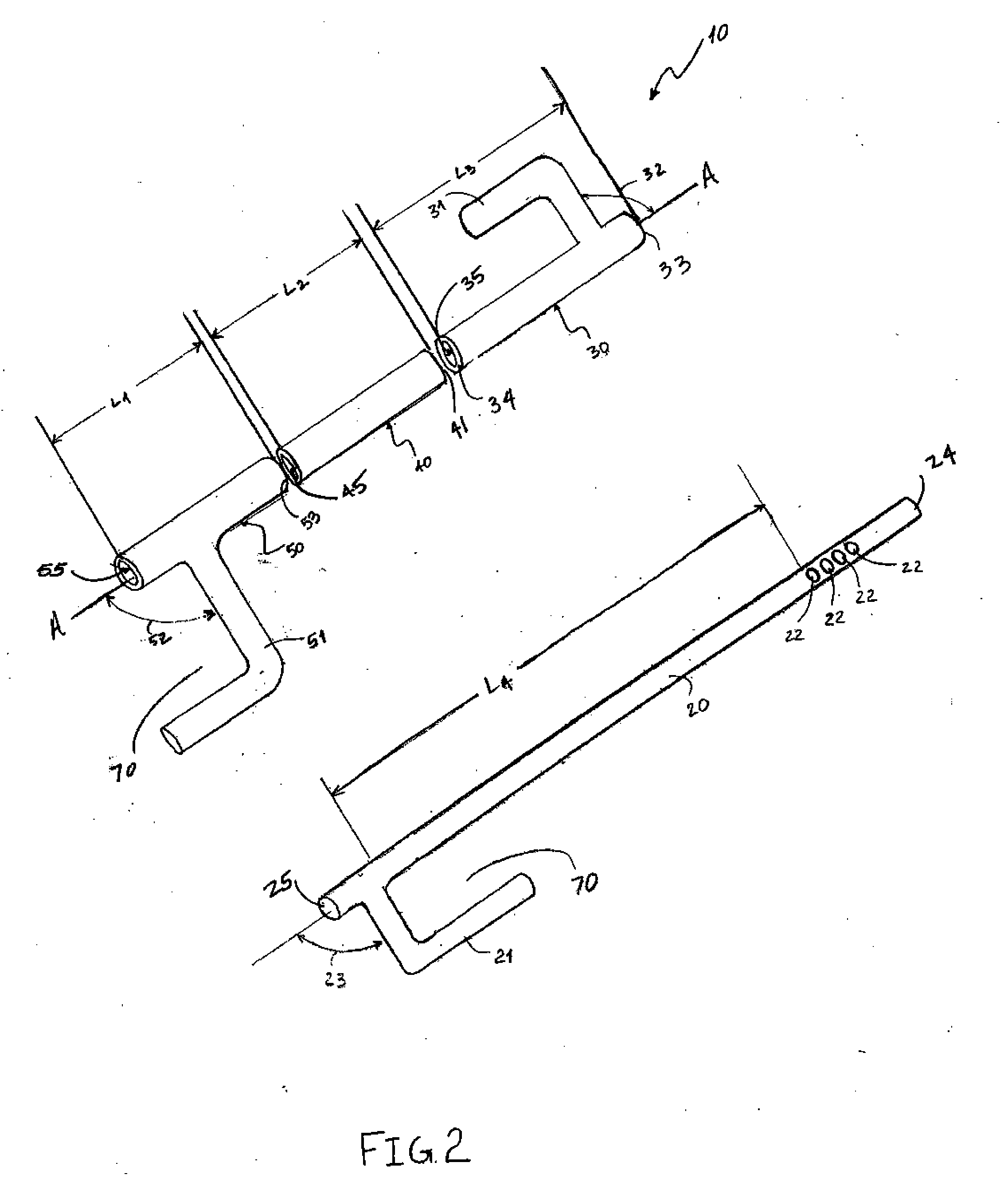
[0017]Device 10 comprises an elongated cylindrical body 20, a first / lower sleeve 50, a second / upper sleeve 30 and a third / middle sleeve 40. As will be discussed in more detail below, sleeves 30, 40, 50 are hollow tubular structures, that can circumferentially surround body 20.

[0018]Body 20 is a solid cylindrical rod structure comprising an upper end 24 and a lower end 25. The invention is not so limited, however, and body 20 could be a rectangular, square, or other shaped rod or bar. The body 20 further comprises a major axis A-A extending from the upper end 24 to the lower end 25. The upper end 24 may also be considered a proximal end and the lower end 25 may be considered a distal end. Cylindrical body 20 is preferably con...


PUM


Abstract

An anti-theft device for automobiles is disclosed. Generally the device includes an elongated rod extending between the steering wheel and the shaft of a brake pedal of an automobile; an L-shaped member extends from the rod and abuts the underside of the brake pedal; a lower tubular structure that can be slid over the rod; a second L-shaped member extending from the lower tubular structure that contacts the first L-shaped member and creates a passageway having a substantially enclosed perimeter in which the shaft of the brake pedal is located; an upper tubular structure that can be slid over the rod; a third L-shaped member extends from the upper tubular structure and attaches to the steering wheel; and means for locking the device that prohibits substantial movement of the upper tubular structure.

Description

CROSS-REFERENCE TO RELATED APPLICATION[0001]The present application claims the benefit of U.S. Provisional Application Ser. No. 60 / 874,599 filed on Dec. 12, 2006, the entirety of which is hereby incorporated by reference.FIELD OF THE INVENTION[0002]The present invention relates generally to automobile anti-theft devices. More specifically, the present invention relates to an automobile brake and steering wheel locking device.BACKGROUND OF THE INVENTION[0003]Automobile anti-theft devices are known in the prior art. U.S. Pat. Nos. 5,005,391; 5,671,620; 5,704,233; 6,439,005 and 6,439,013 each disclose automotive anti-theft devices that engage the brake or gas pedal shafts and the steering wheel and / or the steering wheel spokes as a means for preventing theft of the vehicle.[0004]While these devices fulfill their respective objectives and requirements, these prior art devices all suffer from various deficiencies. For example, such devices are complicated to use and expensive to manufact...

Claims


Application Information

Patent Timeline
IPC IPC(8): B60R25/02
CPCB60R25/0221Y10T70/5894
Inventor DAVIS, ROSS
Owner DAVIS ROSS
Why Eureka
Try Eureka