Power take-off system and gas turbine engine assembly including same

Inactive Publication Date: 2008-06-26
GENERAL ELECTRIC CO
View PDF17 Cites 122 Cited by
  • Summary
  • Abstract
  • Description
  • Claims
  • Application Information

AI Technical Summary

Benefits of technology

[0004]In one aspect, a method for assembling a gas turbine engine including a core gas turbine engine, a low-pressure turbine, a starter, and a generator is provided. The method includes coupling a starter to t

Problems solved by technology

Over time, continued operation with increased thrust levels during such idle operations may increase ma

Method used


Image

  • Power take-off system and gas turbine engine assembly including same
  • Power take-off system and gas turbine engine assembly including same
  • Power take-off system and gas turbine engine assembly including same

Examples


Embodiment Construction

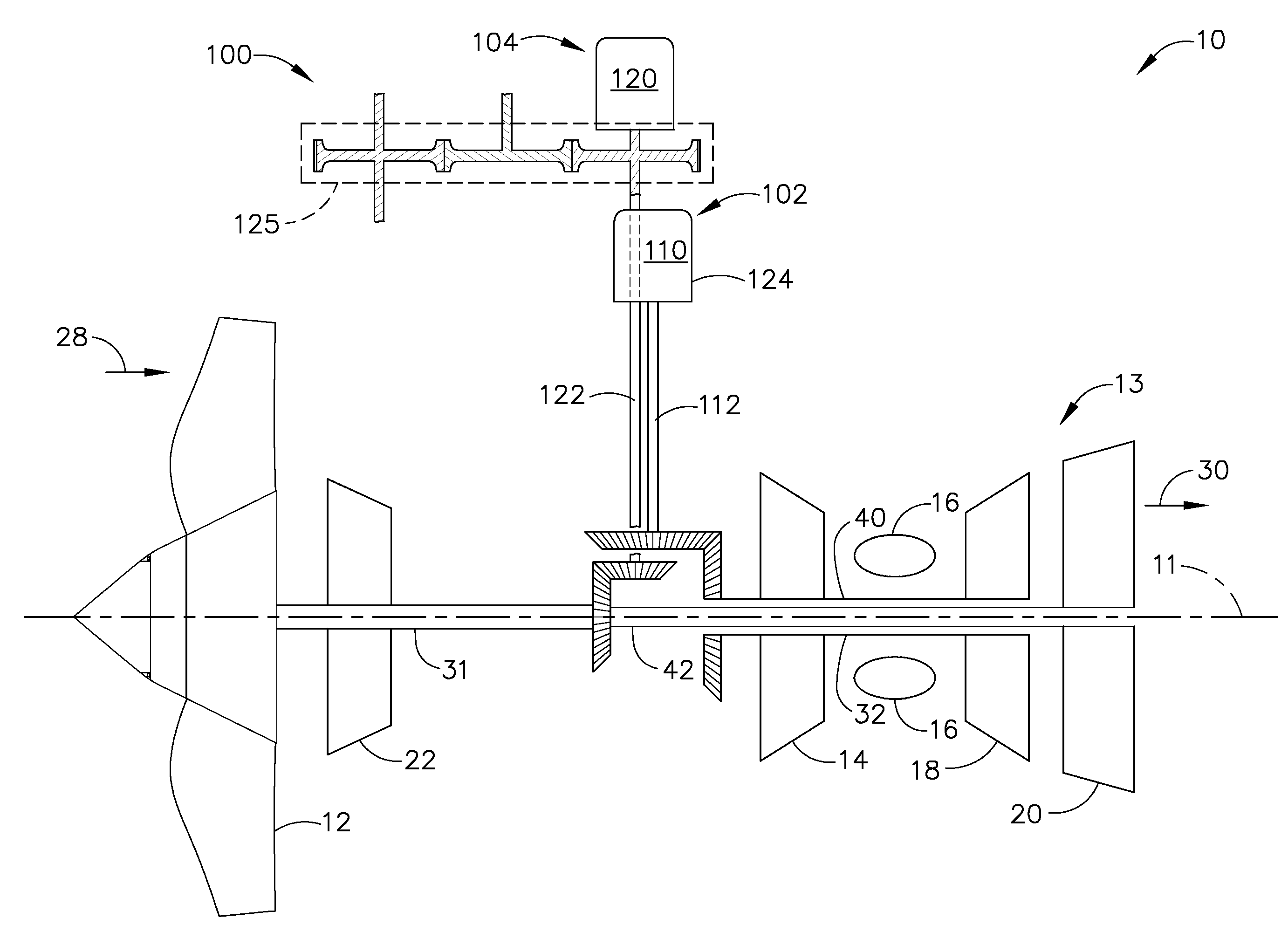
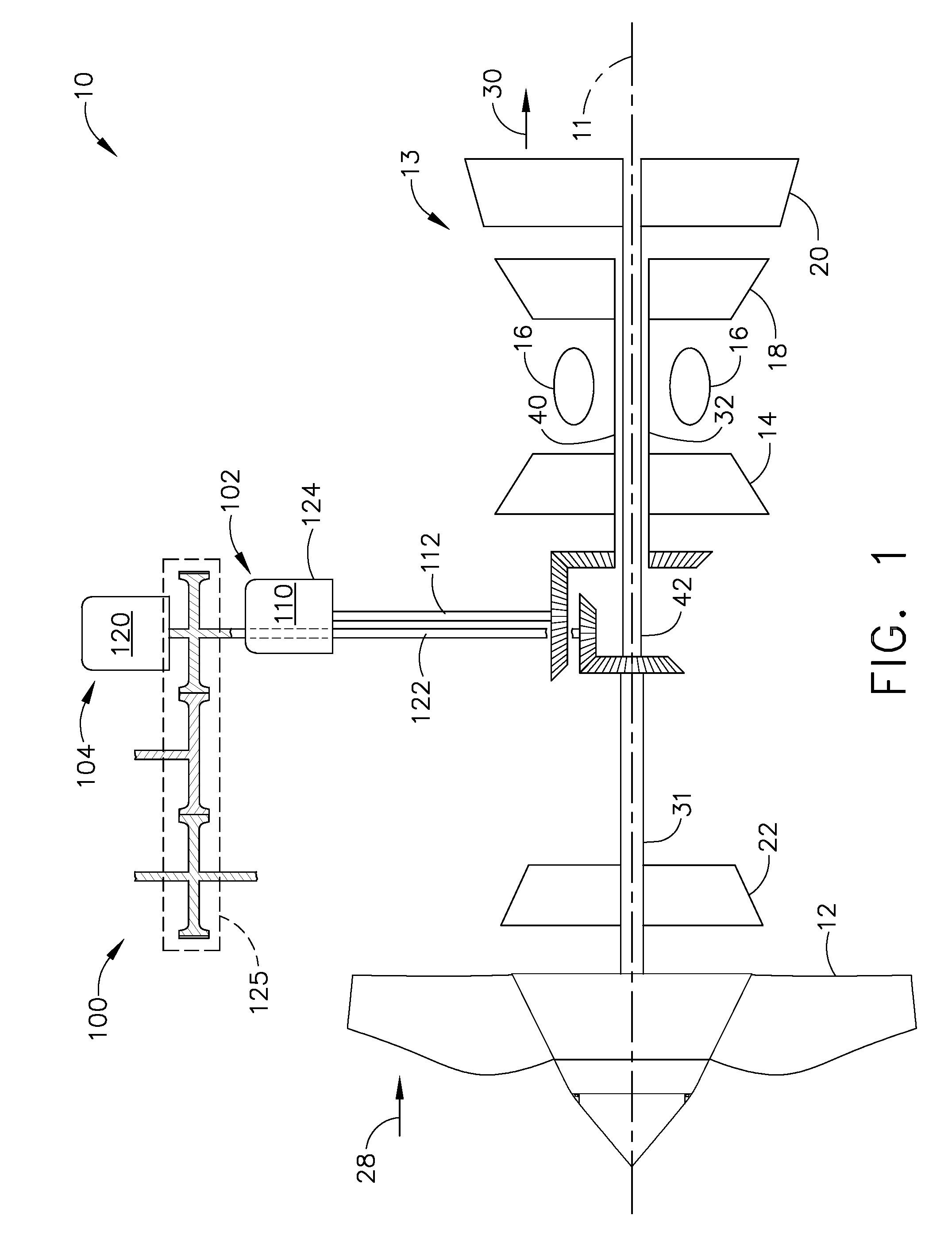
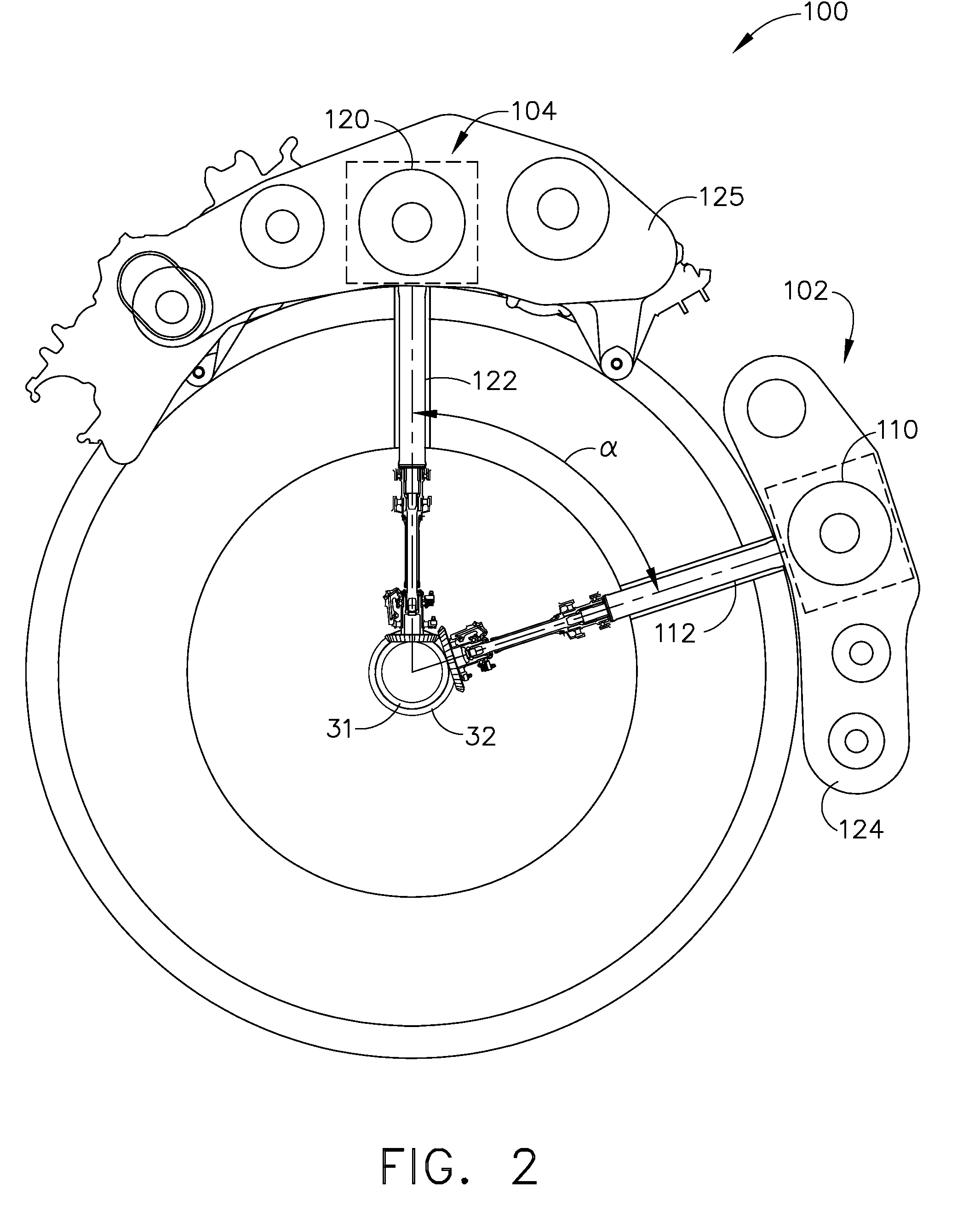
[0013]FIG. 1 is a cross-sectional view of a gas turbine engine assembly 10 having a longitudinal axis 11. FIG. 2 is a an end view of a portion of the exemplary power take-off system shown in FIG. 1. Gas turbine engine assembly 10 includes a fan assembly 12 and a core gas turbine engine 13. Core gas turbine engine 13 includes a high-pressure compressor 14, a combustor 16 that is disposed downstream from high-pressure compressor 14, and a high-pressure turbine 18 that is coupled to high-pressure compressor 14 via a first shaft 32. In the exemplary embodiment, gas turbine engine assembly 10 also includes a low-pressure turbine 20 that is disposed downstream from core gas turbine engine 13, a multi-stage booster compressor 22, and a shaft 31 that is used to couple fan assembly 12 and booster compressor 22 to low-pressure turbine 20. Gas turbine engine assembly 10 has an intake side 28 and an exhaust side 30. In the exemplary embodiment, gas turbine engine assembly 10 is a two spool engi...


PUM

PropertyMeasurementUnit
Angleaaaaaaaaaa
Angleaaaaaaaaaa
Angleaaaaaaaaaa

Abstract

A power take-off system for a gas turbine engine includes a starter coupled to a first spool using a first shaft, and a generator coupled to the second spool using a second shaft, the first shaft is circumferentially offset by the second shaft by an angle α. A method of assembling a gas turbine engine assembly that includes the power take-off system, and a gas turbine engine assembly including the power take-off system are also described.

Description

BACKGROUND OF THE INVENTION[0001]This invention relates generally to gas turbine engines, and more specifically to a dual input / output power take-off system configured to start the gas turbine engine and also configured to generate electrical power.[0002]At least some known gas turbine engines used with aircraft include a core engine having, in serial flow arrangement, a compressor which compresses airflow entering the engine, a combustor which burns a mixture of fuel and air, and low and high-pressure turbines which extract energy from airflow discharged from the combustor to generate thrust.[0003]As aircraft accessory power demands have increased, there also has been an increased need to run the gas turbine engines at idle speeds that may be higher than other engines not subjected to increased power demands. More specifically, increasing the gas turbine engine idle speed enables the increased power demands to be met without sacrificing compressor stall margins. However, the increa...

Claims


Application Information

Patent Timeline
IPC IPC(8): F16H37/00
CPCF02C7/32F05D2220/50Y10T29/4932F05D2260/4031Y02T50/671F05D2220/76Y02T50/60
Inventor MONIZ, THOMAS ORYSCHILLING, JAN CHRISTOPHERORLANDO, ROBERT JOSEPHPATT, RAYMOND FELIX
Owner GENERAL ELECTRIC CO
Why Eureka
Try Eureka