Piston top chamfer design to reduce noise and friction

a top chamfer and chamfer technology, applied in the field of pistons, can solve the problems of increased piston noise, increased piston noise, and more likely to be an issue, so as to increase the level of lubrication, increase and increase the effect of the noise of the piston

Inactive Publication Date: 2008-06-26
GM GLOBAL TECH OPERATIONS LLC
View PDF2 Cites 13 Cited by
  • Summary
  • Abstract
  • Description
  • Claims
  • Application Information

AI Technical Summary

Benefits of technology

[0004]While scuffing and scoring of the piston skirt and the adjacent cylinder wall results in increased noise, increased piston noise can also occur without the presence of scuffing or scoring. When adequate lubrication is provided to the piston and skirt, the piston skirt and cylinder wall are protected against scuffing and scoring. Enhancing this level of lubrication, particularly at the middle portions of the piston skirt advantageously acts to further reduce piston noise. Unlike scuffing and scoring that may occur with the engine operating under significant load, piston noise is more likely to be an issue in low speed, no load or low lead engine operating conditions. The present invention is directed to a piston configured to enhance lubrication to the middle portions of the piston skirt to reduce this piston noise.

Problems solved by technology

While scuffing and scoring of the piston skirt and the adjacent cylinder wall results in increased noise, increased piston noise can also occur without the presence of scuffing or scoring.
Unlike scuffing and scoring that may occur with the engine operating under significant load, piston noise is more likely to be an issue in low speed, no load or low lead engine operating conditions.

Method used


Image

  • Piston top chamfer design to reduce noise and friction
  • Piston top chamfer design to reduce noise and friction
  • Piston top chamfer design to reduce noise and friction

Examples


Embodiment Construction

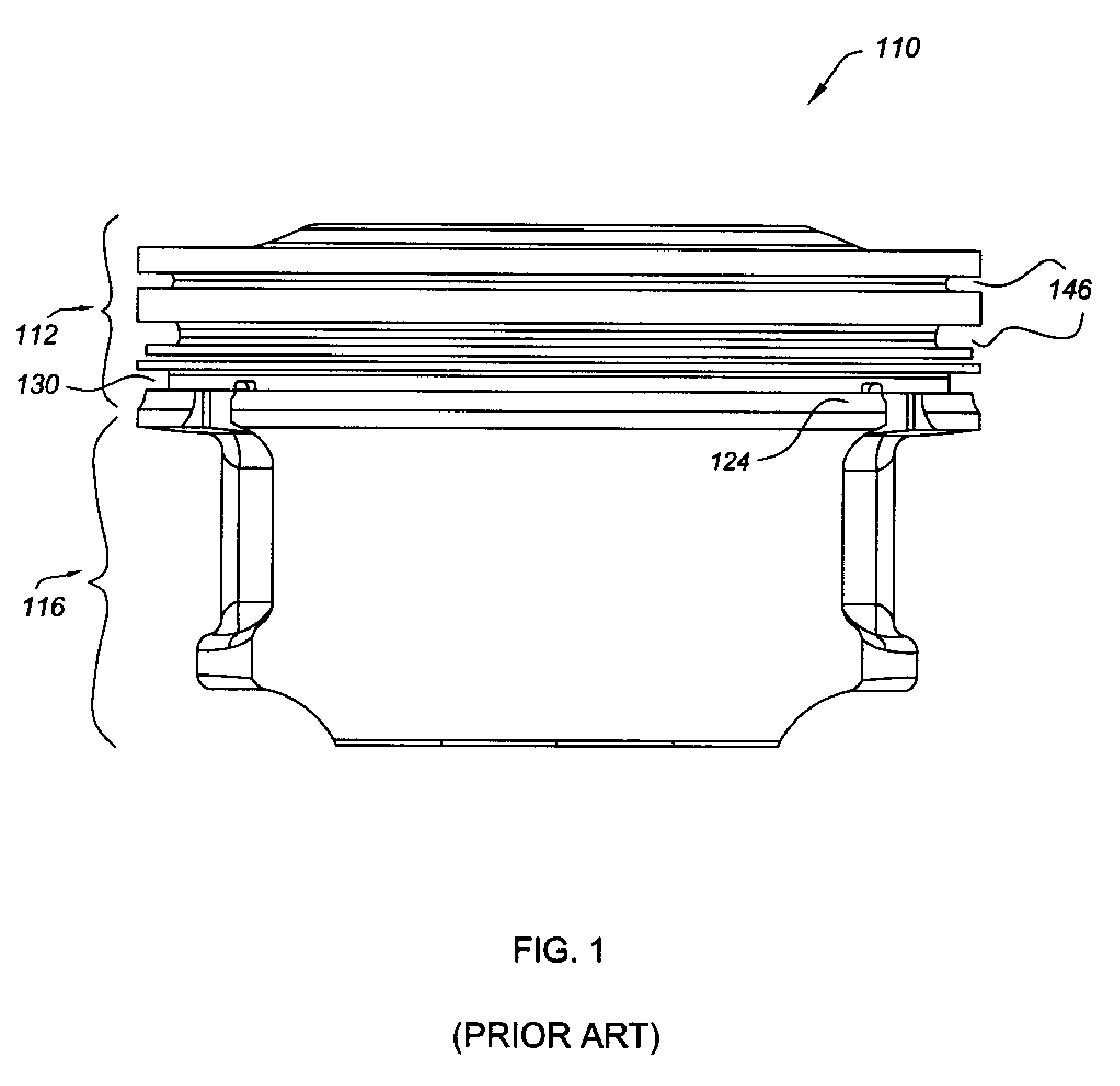
[0021]FIG. 1 illustrates a side view of a piston 110 having a piston head portion 112 and skirt portion 116 provided with a traditional non-tapered top or axially upper chamfer 124. The piston 110 has an oil control ring groove 130 located above and proximate to the top chamfer 124. The top chamfer 124 and oil control ring groove 130 are located below the piston ring grooves 146.

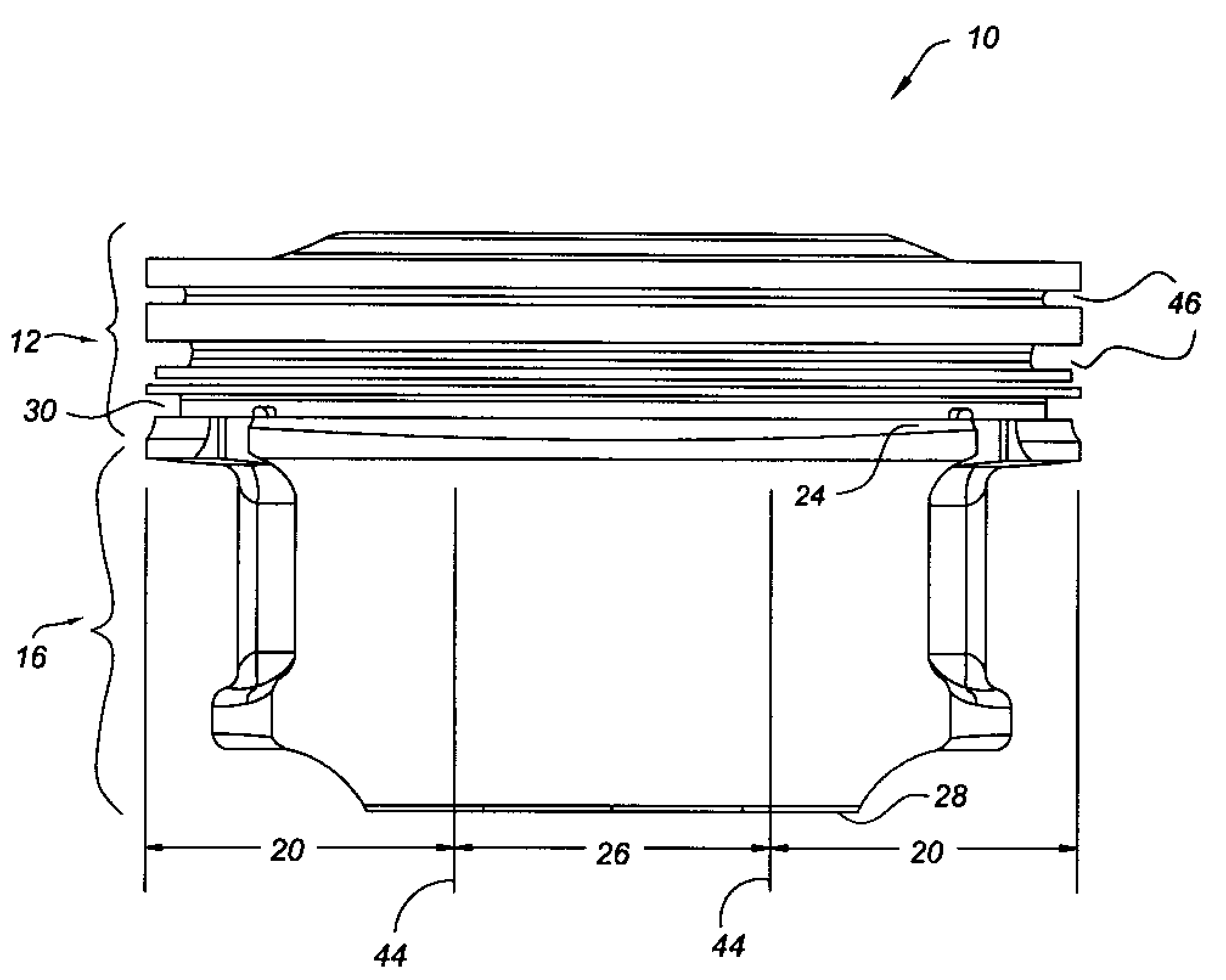
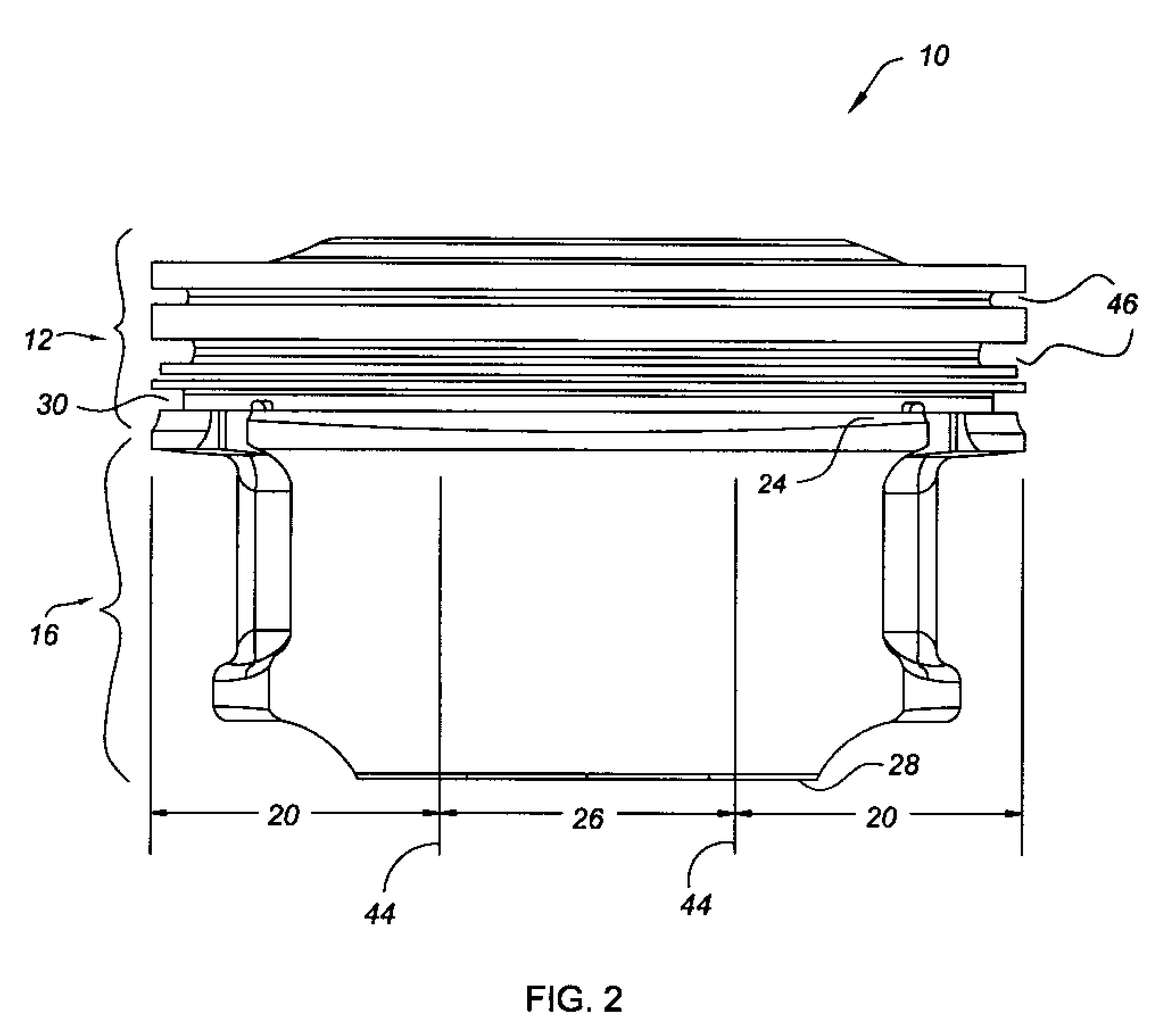
[0022]FIG. 2 illustrates a side view of a piston 10 having a piston head portion 12 and skirt portion 16 equipped with a top chamfer 24 and a bottom chamfer 28. The top chamfer 24 defines a tapered volume profile configured to preferentially store and deliver a larger quantity of oil to the middle skirt portion 26 (depicted as the region between boundary lines 44) to increase lubrication thereat and thereby reduce piston noise, consistent with the present invention. In FIG. 2, the skirt portion 16 of the piston 10 includes a top chamfer 24 located proximate to and directly below the annular oil control ring ...


PUM


Abstract

Disclosed is a piston having a top chamfer functioning as an oil reservoir, the top chamfer designed to reduce piston noise and friction. The top chamfer partially defines a tapered volume or cavity configured to enhance oil flow to the middle portions of the piston skirt so as to increase lubrication during piston up stroke and thereby reduce piston noise and friction.

Description

TECHNICAL FIELD[0001]The present invention is directed to pistons having a head and skirt portions together with a top chamfer designed to channel oil to the center of the piston skirt to reduce piston noise and friction.BACKGROUND OF THE INVENTION[0002]As is known in the art, the oil lubrication of pistons in internal combustion engines, such as automotive engines, may be less than optimum in particular situations and under certain engine operating conditions. A lack of optimum levels of lubrication around portions of the piston or skirt periphery can lead to increased piston noise as well as increased friction, in severe cases leading to increased chance of scoring of the piston skin and cylinder liner or wall. Less than optimum lubrication can result in increased piston noise independent of scuffing, scoring and wear issues.[0003]A greater portion of the side stress developed during piston operation is known to occur in regions referred to as the thrust faces. The thrust faces ar...

Claims


Application Information

Patent Timeline
Patent Type & Authority Applications(United States)
IPC IPC(8): F16J1/08
CPCF01M9/00F16J1/08F02F3/00
Inventor FISHER, JOHN B.SHI, FANGHUISCHROEDER, KENNETH E.
Owner GM GLOBAL TECH OPERATIONS LLC
Why Eureka
Try Eureka