
Material sensitive downhole flow control device

a flow control device and material technology, applied in the field of downhole tools, can solve the problems of prone to occasional production of undesirable water or unwanted effects

Active Publication Date: 2008-06-26
BAKER HUGHES INC
View PDF48 Cites 150 Cited by
  • Summary
  • Abstract
  • Description
  • Claims
  • Application Information

AI Technical Summary

Benefits of technology

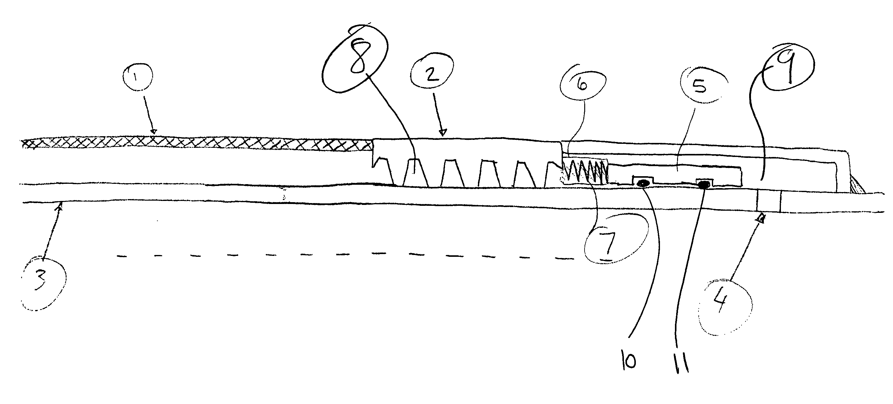
The patent describes a screen section with a valve that can control the flow through it. The valve is opened and closed by a spring that is compressed by a special material that changes its properties when it comes into contact with specific well fluids. This material, called a shape memory polymer, gets softer when it detects water or methane and releases its potential energy to operate the downhole tool. The technical effect of this invention is to provide a reliable and efficient way to control the flow of fluids in well tools, which can improve the efficiency and accuracy of well drilling operations.

Problems solved by technology

Wells that are in production are prone to occasional production of undesirable water or unwanted gasses such as methane, for example.

Method used


Image

  • Material sensitive downhole flow control device
  • Material sensitive downhole flow control device

Examples


Embodiment Construction

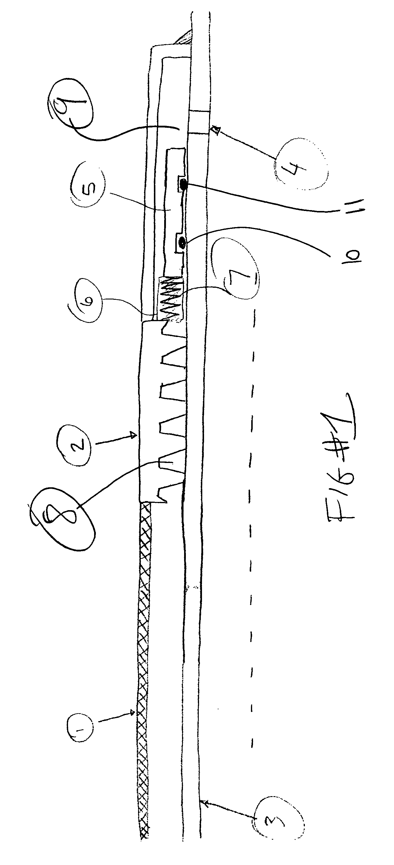
[0007]FIG. 1 illustrates a screen 1 that has a base pipe 3 behind it so that flow through the screen has to go through a spiral path 8 in housing 2 to reach a port 4. Housing 2 covers port 4 creating an annular space 9 in which is located a sliding sleeve 5 that has spaced apart seals 10 and 11. In the FIG. 1 position, the friction force of the seals 10 and 11 holds the sleeve 5 in position for run in and production through the screen 1. This happens because the sleeve 5 is in pressure balance in annular space 9. A source of potential energy, such as a spring 7 is preferably embedded or otherwise held compressed by a material 6 which is a part of the actuating component. The preferred material is of the type that changes physical properties or dimension when in the presence of a material that is sought to be excluded from flowing through the screen 1 in significant quantities. A shape memory material that is sensitive to a specific material or materials can be used as material 6. On...


PUM


Abstract

A screen section has a valve assembly to control flow through it. The valve is open and has a closure spring held compressed by a shape memory material that responds to the presence of a specific well fluid or fluids so that its property changes to allow the spring to deliver the stored potential energy to the valve member to close it when the specific well fluid or fluids are detected. The preferred material is a shape memory polymer that, for example, is sensitive to the presence of water or methane and gets softer to release the potential energy source to operate the downhole tool.

Description

FIELD OF THE INVENTION[0001]The field of the invention is downhole tools that can be actuated by a material that responds to the presence of certain well fluids so as to actuate a tool.BACKGROUND OF THE INVENTION[0002]Wells that are in production are prone to occasional production of undesirable water or unwanted gasses such as methane, for example. When these situations arise it is necessary to cut the production flow and take production from elsewhere in the wellbore or even to drill a new lateral to get away from the migration of those contaminants into the production string.[0003]Typically, the production takes place through screens, with or without a gravel pack in the annulus around the screen. In the event of production of a contaminant, it is advantageous to cut off the production flow and to do it automatically at the initial detection of the presence of such a material.[0004]The present invention has many applications and is suited to selectively cut off flow to a screen s...

Claims


Application Information

Patent Timeline
Patent Type & Authority Applications(United States)
IPC IPC(8): E21B43/12
CPCE21B34/06E21B43/08E21B34/14E21B34/08E21B23/04
Inventor O'MALLEY, EDWARD J.RICHARD, BENNETT M.
Owner BAKER HUGHES INC
Learn More