Crystal unit having stacked structure

a crystal unit and stacked technology, applied in the direction of windings, generators/motors, device details, etc., can solve the problems of difficult to secure air tightness, vibration members were susceptible to an effect, and not necessarily reliable air sealing, so as to achieve the effect of easy sealing of air tightness

Inactive Publication Date: 2008-06-26
NIHON DEMPA KOGYO CO LTD
View PDF13 Cites 11 Cited by
  • Summary
  • Abstract
  • Description
  • Claims
  • Application Information

AI Technical Summary

Benefits of technology

[0016]According to such configuration, the first and second electrode through-holes are formed in the first crystal plate and at least one of the second and third crystal plate, and a sealing path formed by the electrode through-holes can be prolonged. Therefore, airtightness of the crystal unit can be secured.
[0017]In the crystal unit of the present invention, the first and second electrode-through-holes may be formed at different positions of the first crystal plate, and the second or third crystal plate to have a shape of crank. When forming in a shape of crank can maintain air sealing of at least either the first electrode through-hole or the second electrode through-hole, airtightness is secured. In this case, the first electrode through-hole provided in the first crystal plate can be formed of a third and fourth electrode through-holes provided at different positions. Configuring the first electrode through-hole by the third and fourth electrode through-holes provides three electrode through-holes in total, and thereby airtightness can be more easily secured.
[0018]Alternatively, in the crystal unit of the present invention

Problems solved by technology

However, it is thought that the via-hole serving as electrode through-hole 6 is formed of a sintered member of chromium, and the via-hole is not integrated with quartz crystal by interatomic bond, and does not necessarily provide re

Method used


Image

  • Crystal unit having stacked structure
  • Crystal unit having stacked structure
  • Crystal unit having stacked structure

Examples


first embodiment

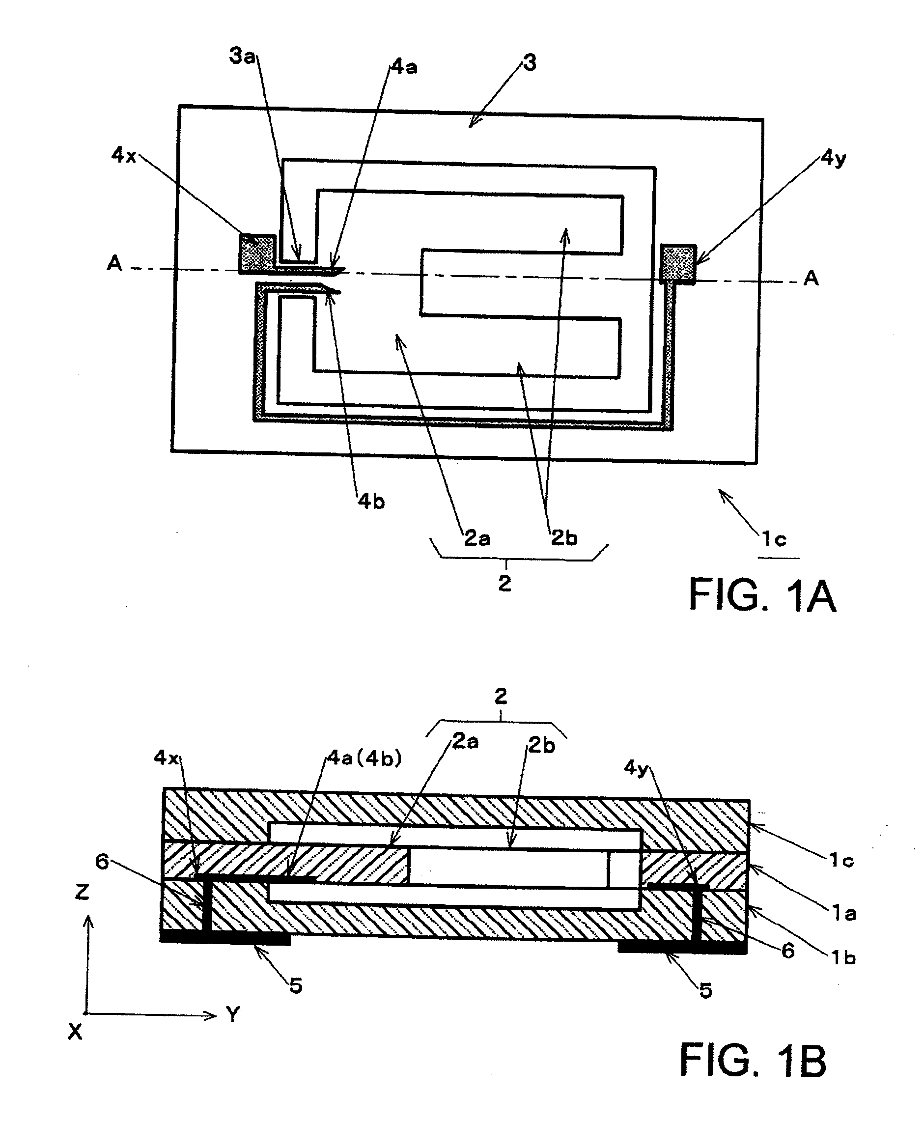
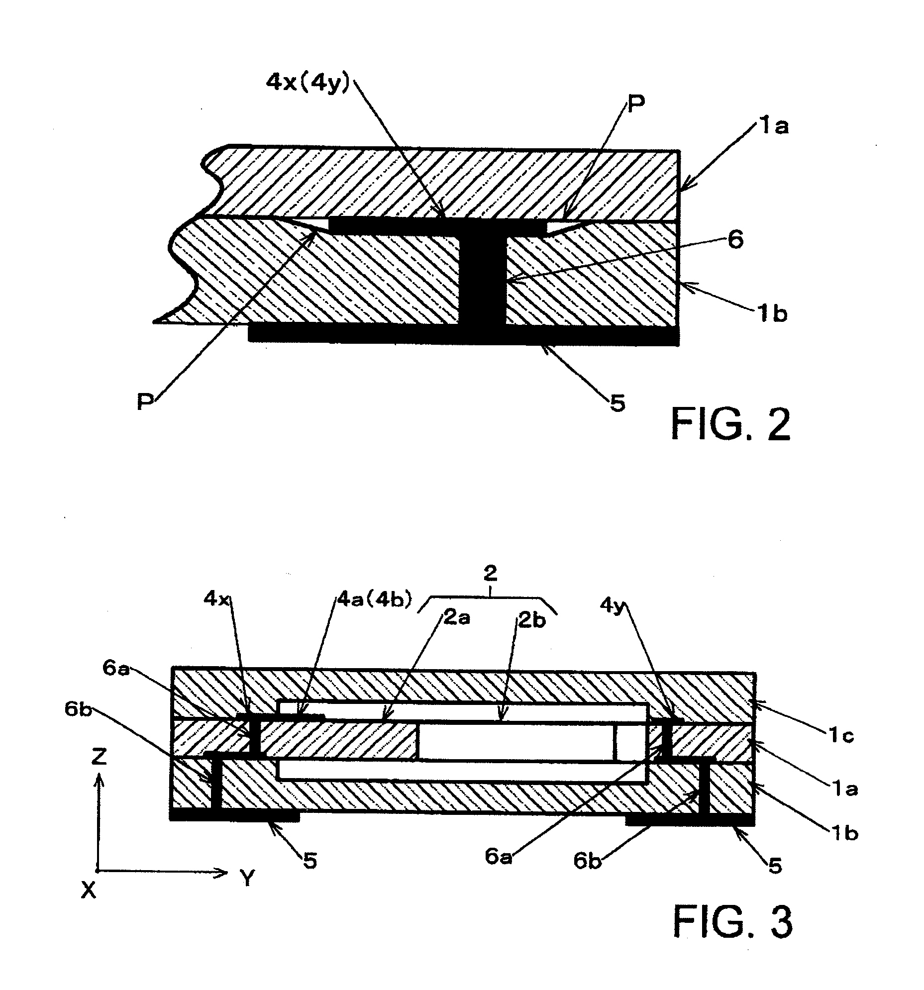
[0032]In FIGS. 3, 4A and 4B illustrating a crystal unit of a first embodiment of the present invention, same reference symbols will be given to the same components as in FIGS. 1A, 1B and 2 to avoid or simplify redundant explanations.

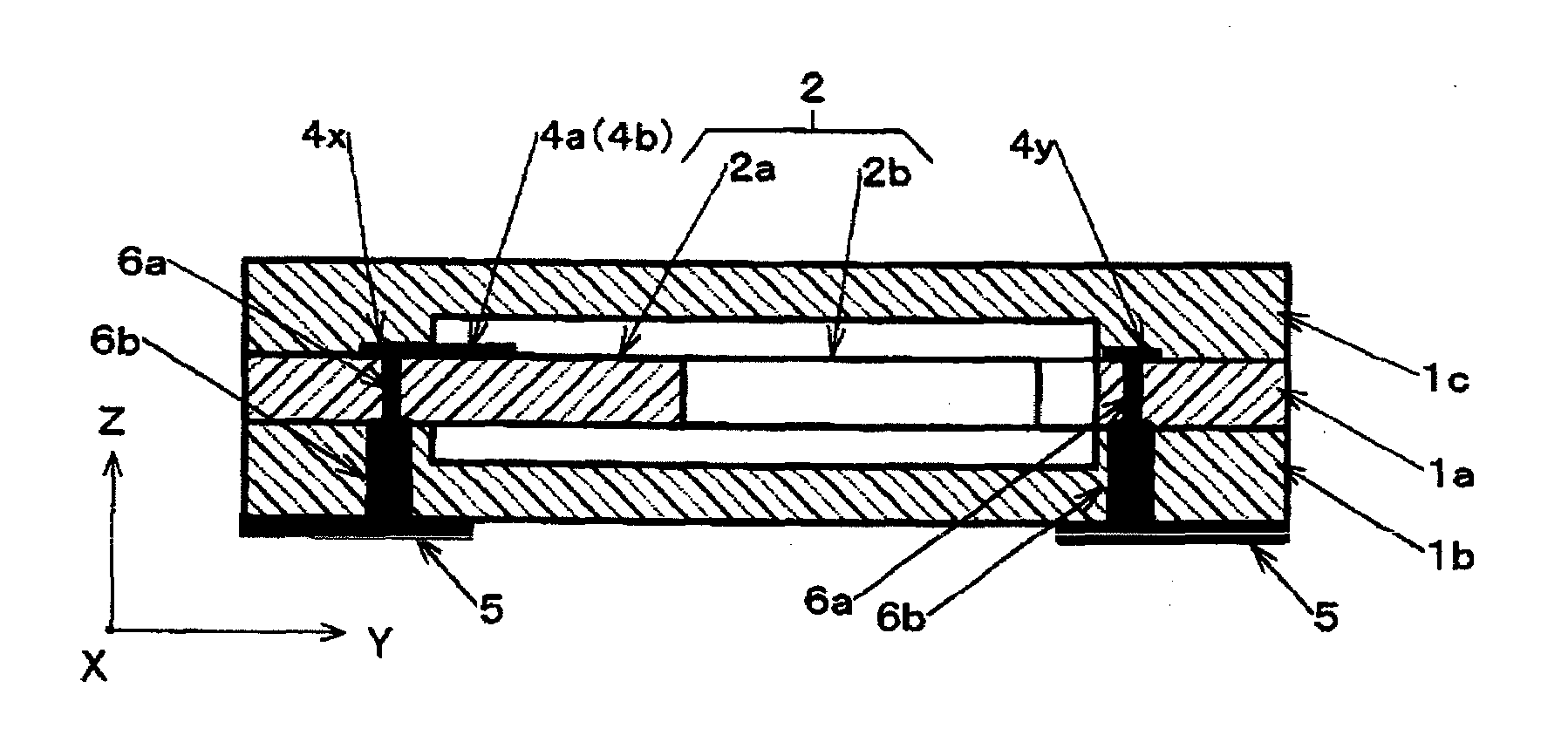
[0033]A crystal unit according to the first embodiment, as described above, includes: first quartz crystal plate 1a including a vibration member and frame portion 3 to which the vibration member links; and second and third quartz crystal plates 1b and 1c each of which functions as a cover for the vibration member. Each of second and third crystal plates 1b and 1c has a concave portion in an area opposite to the vibration member. Then, to both principal surfaces of frame portion 3 in first crystal plate 1a, open end surfaces to form outer circumferential portions of the concave portions in second and third crystal plates 1b and 1c are joined by direct bonding. As the vibration member, first crystal plate 1a has tuning-fork-like crystal blank 2 as describe...

second embodiment

[0042]FIG. 6 shows, in a cross-section view, a configuration especially of both end portions of a crystal unit of a second embodiment of the present invention.

[0043]In the crystal unit of the second embodiment, each of first electrode through-holes 6a on both end portions of one principal surface of first crystal plate 1a, that is, the vibrating member, to which a pair of extending electrodes 4a and 4b extend, is formed of third and fourth electrode through-holes 6c and 6d provided adjacent to each other in first crystal plate 1a. Then, on the other principal surface side of first crystal plate 1a, third and fourth electrode through-holes 6c and 6d are electrically connected to each other via electrode pads 8x and 8y and the like including an electrically conducting path. Fourth electrode through-hole 6d is connected to second electrode through-hole 6b provided in third crystal plate 1c via electrode pads 9x and 9y. Second electrode through-hole 6b is connected to external terminal ...

third embodiment

[0048]A crystal unit of a third embodiment shown in FIG. 7 is similar to that of the first embodiment, but it is a different from the crystal unit of the first embodiment in that first electrode through-hole 6a provided in first crystal plate 1a and, for example, second electrode through-hole 6b provided in second crystal plate 1b are arranged to be connected to each other in alignment. Extending electrodes 4a and 4b are extended to the outer surface of second crystal plate 1b through these electrode through-holes 6a and 6b, and connected to external terminals 5 provided on the outer surface of second crystal plate 1b.

[0049]Next, a manufacture method of the crystal unit will be described.

[0050]First, second and third crystal plates 1b and 1c are joined by direct bonding to first crystal plate 1a in which the excitation electrodes are formed and which has, for example, electrode pads 4x and 4y extending from extending electrodes 4a and 4b on one end side and the other end side of on...


PUM


Abstract

A stacked crystal unit includes: a first crystal plate in which a vibration member links to an outer circumferential frame portion, and a pair of extending electrode extends to the frame portion from excitation electrodes; and a second and third crystal plates which have a concave portion in an area opposite to the vibration member and whose open end surfaces are joined by direct bonding to both principal surfaces of the frame portion in the first crystal plate. The extending electrodes are electrically extended to an outer surface of at least one of the second and third crystal plates via electrode through-holes provided in the frame portion. The electrode through-hole includes: a first electrode through-hole penetrating through the frame portion from the principal surface of the frame portion where the extending electrode extends; and a second electrode through-hole provided in the second or third crystal plate.

Description

BACKGROUND OF THE INVENTION[0001]1. Field of the Invention[0002]The present invention relates to a crystal unit having a stacked structure in which a plurality of crystal plates are joined to each other by direct bonding, and particularly to a configuration for extending an electrode to an outer surface of a crystal unit.[0003]2. Description of the Related Art[0004]A crystal unit having a configuration in which a vibration member formed by a quartz crystal plate is hermetically encapsulated in a package is known as a frequency control device, and is incorporated in an oscillation circuit and a tuning circuit in various electronic apparatuses. As electronic apparatuses have recently been miniaturized, the crystal unit also is required to be miniaturized and simplified in configuration, and accordingly, there has been proposed a crystal unit having a stacked structure in which crystal plates are joined to each other by direct bonding using, for example, siloxane bond. A crystal unit h...

Claims


Application Information

Patent Timeline
IPC IPC(8): H01L41/02
CPCH03H9/1035H03H9/0595
Inventor YOSHIMATSU, MASAHIROKUROSAWA, TAMOTSUONO, KOZO
Owner NIHON DEMPA KOGYO CO LTD
Why Eureka
Try Eureka