Remote Monitoring Device

Inactive Publication Date: 2008-06-26
HUANG MARC
View PDF9 Cites 5 Cited by
  • Summary
  • Abstract
  • Description
  • Claims
  • Application Information

AI Technical Summary

Benefits of technology

[0011]The primary objective of this invention is to provide a remote monitoring device with illuminating, sensing, and sound emitting functions integrated therein in order to detect any variation of the surr

Problems solved by technology

However, this system suffers from a disadvantage in that some people can deliberately evade the passive monitoring system.
The problem with this system is that a sufficient amount of storage space has to be allocated for such a large number of images, and numerous irrelevant images contained therein not only unnecessarily consume power, but also necessitate image filtering in order to obtain cr

Method used


Image

  • Remote Monitoring Device
  • Remote Monitoring Device
  • Remote Monitoring Device

Examples


Embodiment Construction

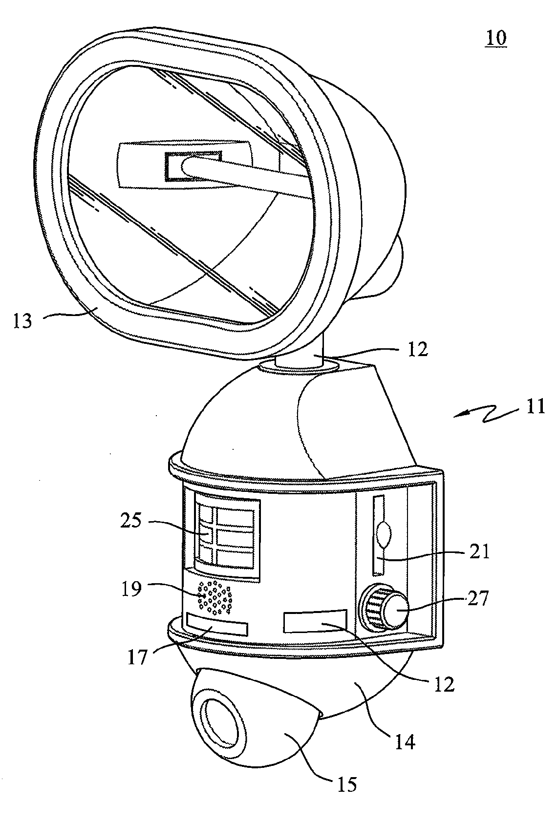
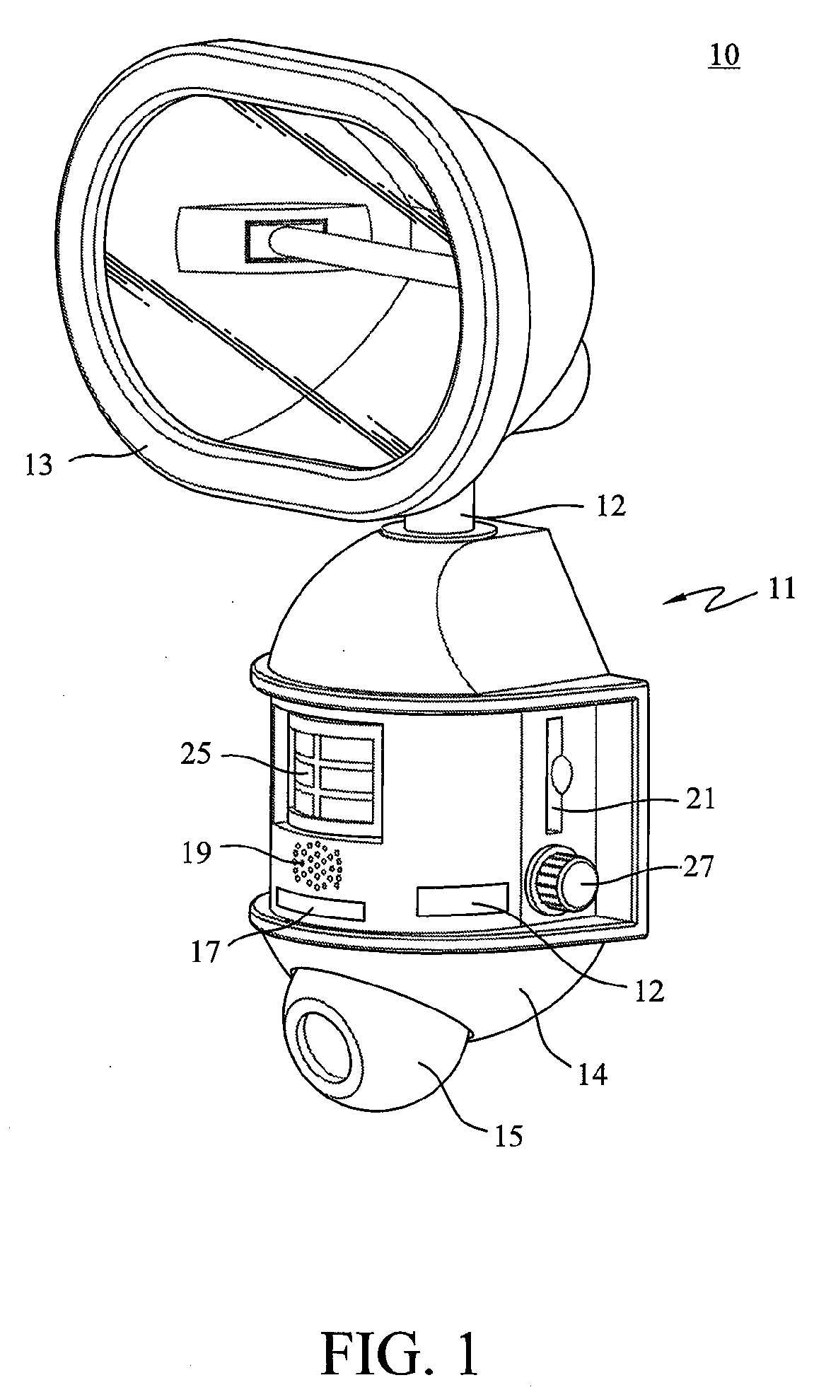
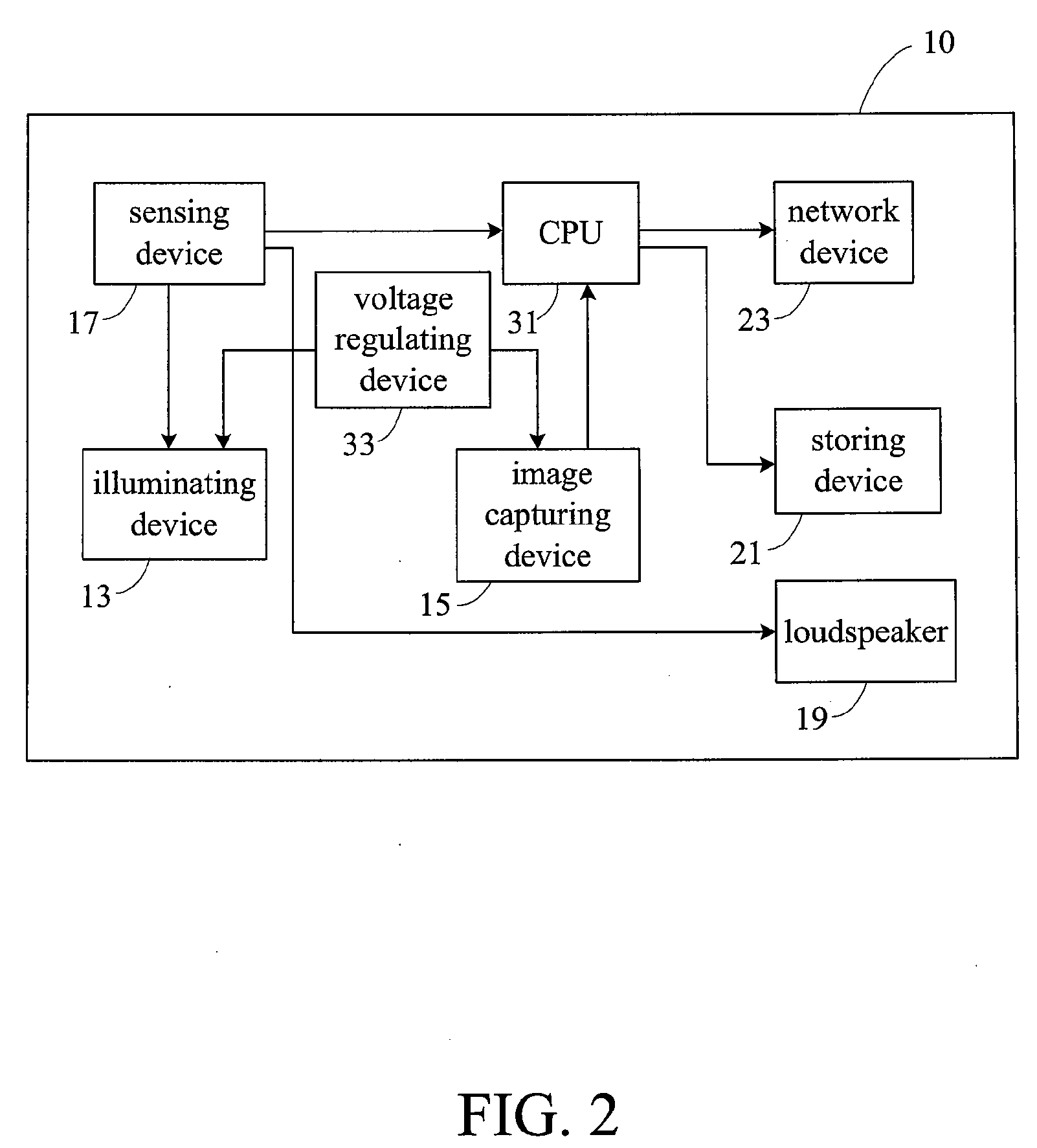
[0019]Referring to FIG. 1 and FIG. 2, FIG. 1 depicts a perspective view of a monitoring device 10 of the present invention, and FIG. 2 depicts a basic block diagram of connections in the system.

[0020]The monitoring device 10 of the present invention comprises a body 11, and an illuminating device 13, an image capturing device 15, a sensing device 17, and a loudspeaker 19 disposed on the body 11. The sensing device 17 is electrically connected with the illuminating device 13 and the image capturing device 15, and the loudspeaker 19 is electrically connected with the sensing device 17. The illuminating device 13 has at least one lamp disposed therein to provide an indicating light source during the operation of the monitoring device 10.

[0021]Preferably, the sensing device 17 is a motion sensor, such as a private infrared ray (PIR) sensor, which can be triggered by a variation of an image of the surrounding environment. When the sensing device 17 senses that the environment surrounding...


PUM


Abstract

A remote monitoring device comprising an illuminating device, an image capturing device, a sensing device, and a loudspeaker is provided. When the sensing device senses a change in the surrounding environment, the illuminating device lights up, the image capturing device generates image signals, and the loudspeaker activates.

Description

[0001]This application claims the benefits of the priority based on Taiwan Patent Application No. 095222416 filed on Dec. 20, 2006; the disclosures of which are incorporated by reference herein in their entirety.CROSS-REFERENCES TO RELATED APPLICATIONS[0002]Not applicable.BACKGROUND OF THE INVENTION[0003]1. Field of the Invention[0004]The present invention relates to a remote monitoring device. In particular, the invention relates to a remote monitoring device that is adapted to sense variations in the surroundings, emit sounds, and record images.[0005]2. Descriptions of the Related Art[0006]With the advancement of imaging technology, users nowadays can utilize remote monitoring devices to monitor the state of a remote location. For example, remote monitoring devices may be used by security guards to monitor various floors of a building, by express railway clerks to monitor the interior of railway cars, by parents at work to monitor children or housekeepers at home, by home owners t...

Claims


Application Information

Patent Timeline
IPC IPC(8): G08B21/00
CPCG08B3/10G08B13/196G08B13/19G08B5/36
Inventor HUANG, MARC
Owner HUANG MARC
Why Eureka
Try Eureka