
Computer vision based touch screen

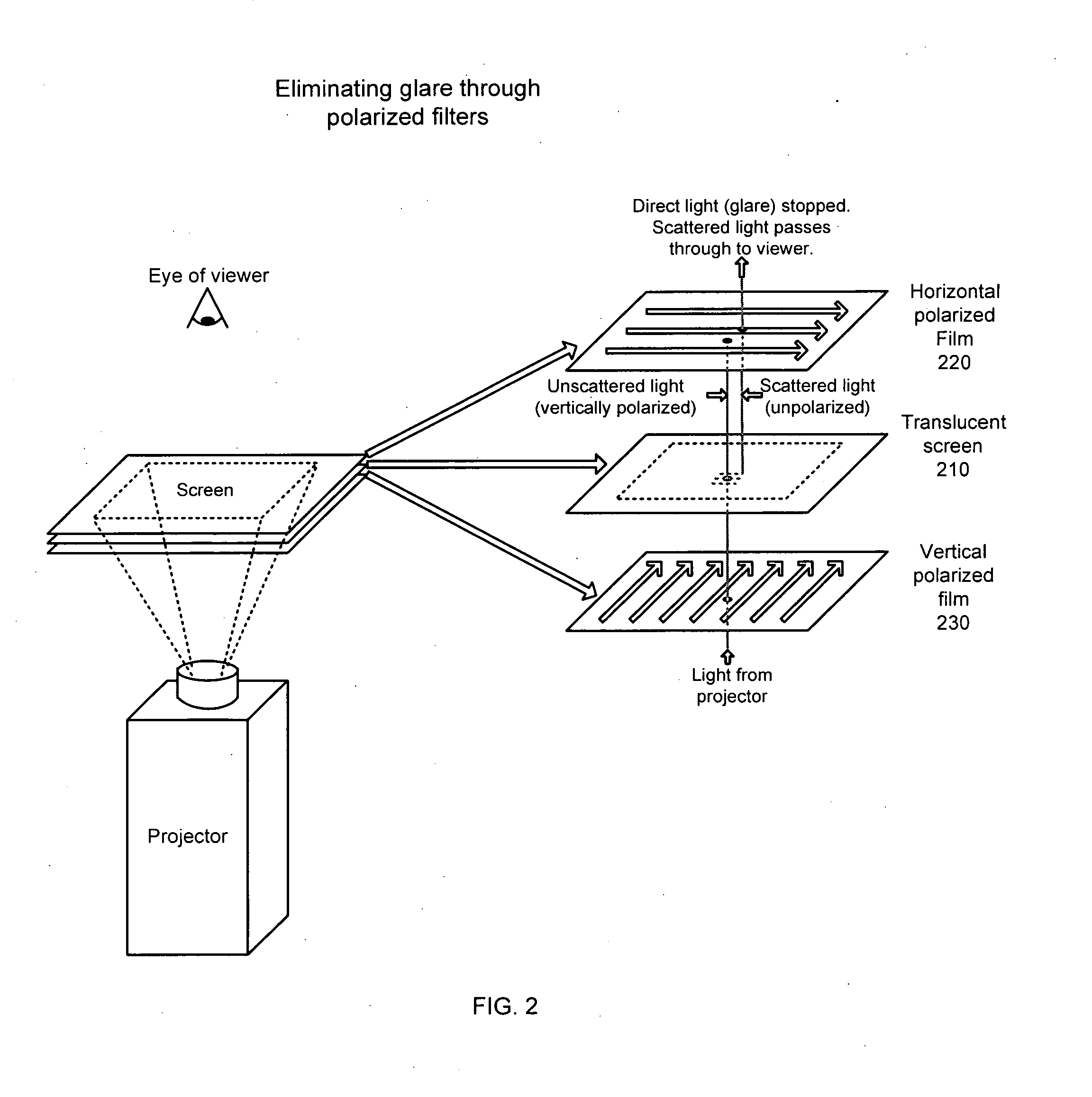
a touch screen and computer vision technology, applied in the field of self-contained interactive video display system, can solve the problems of not being able to discern the shape of input input, the display is not typically interactive between users and the display, etc., and achieve the effect of reducing glar

Inactive Publication Date: 2008-06-26
MICROSOFT TECH LICENSING LLC
View PDF98 Cites 346 Cited by
  • Summary
  • Abstract
  • Description
  • Claims
  • Application Information

AI Technical Summary

Benefits of technology

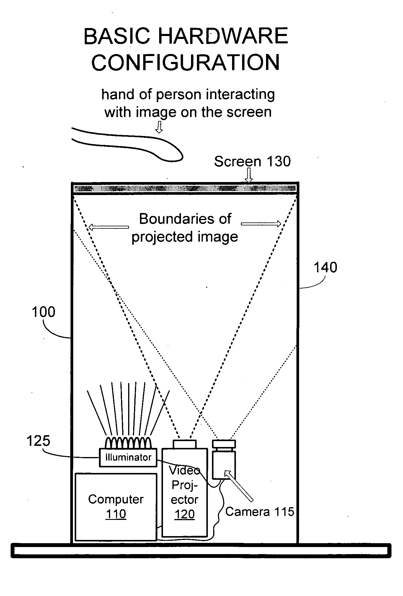
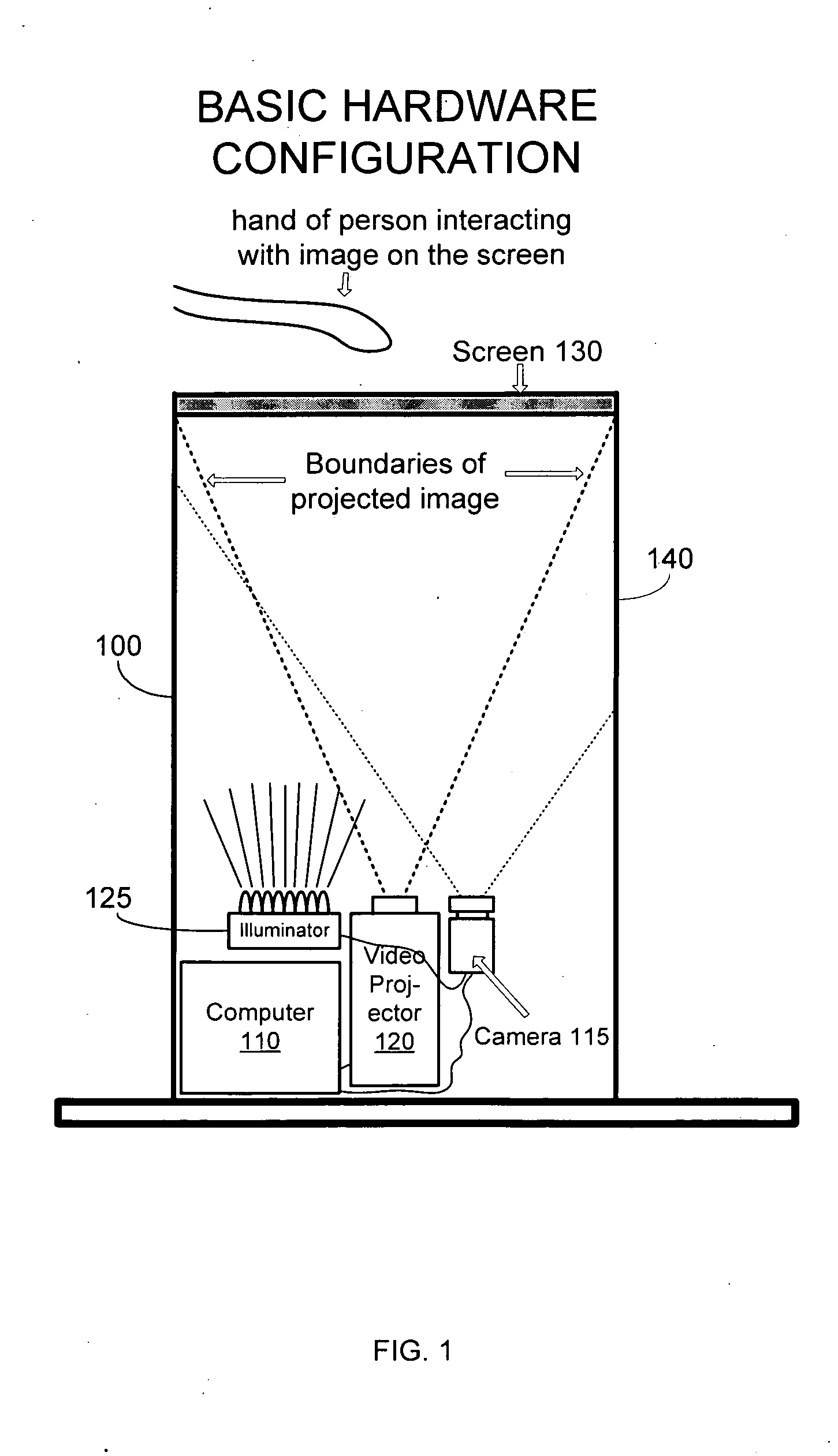
The present invention is a self-contained interactive video display system that allows users to interact with a visual image on a screen. The system includes a projector, a screen, an illuminator, and a camera. The projector projects the visual image onto the screen, and the screen is at least partially transparent to light detectable to the camera. The camera detects interaction of an illuminated object with the visual image, and the system changes the visual image in response to the interaction. The system can be used in various settings, such as in retail stores, and provides touchscreen functionality when the object is proximate the screen. The technical effects of the invention include improved user experience, enhanced advertisement effectiveness, and improved data collection and analysis.

Problems solved by technology

While more engaging than static displays, dynamic displays do not typically provide interactivity between a user and the display.
Moreover, typically touchscreens can only receive one input at any time, and are not able to discern the shape of the input.
Furthermore, because current touchscreens cannot discern the shape of input, they are limited in the type of information that can be presented in response to interaction.

Method used


Image

  • Computer vision based touch screen
  • Computer vision based touch screen
  • Computer vision based touch screen

Examples


Embodiment Construction

[0054]Reference will now be made in detail to various embodiments of the invention, an electronic device for monitoring the presence of objects around a second electronic device, examples of which are illustrated in the accompanying drawings. While the invention will be described in conjunction with these embodiments, it is understood that they are not intended to limit the invention to these embodiments. On the contrary, the invention is intended to cover alternatives, modifications and equivalents, which may be included within the spirit and scope of the invention as defined by the appended claims. Furthermore, in the following detailed description of the invention, numerous specific details are set forth in order to provide a thorough understanding of the invention. However, it will be recognized by one of ordinary skill in the art that the invention may be practiced without these specific details. In other instances, well known methods, procedures, components, and circuits have ...


PUM


Abstract

A self-contained interactive video display system. A projector projects a visual image onto a screen for displaying the visual image, wherein the projector projects the visual image onto a back side of the screen for presentation to a user on a front side of the screen. An illuminator illuminates an object near the front side of the screen. A camera detects interaction of an illuminated object with the visual image, wherein the screen is at least partially transparent to light detectable to the camera, allowing the camera to detect the illuminated object through the screen. A computer system directs the projector to change the visual image in response to the interaction.

Description

CROSS-REFERENCE TO RELATED APPLICATION[0001]This application is a continuation and claims the priority benefit of U.S. patent application Ser. No. 10 / 946,263 filed Sep. 20, 2004 and entitled “Self-contained Interactive Video Display System,” which is a continuation-in-part and claims the priority benefit of U.S. patent application Ser. No. 10 / 160,217 filed on May 28, 2002 and entitled “Interactive Video Display System”; U.S. patent application Ser. No. 10 / 946,414 also claims the priority benefit of U.S. provisional patent application Nos. 60 / 504,375 filed on Sep. 18, 2003; 60 / 514,024 filed on Oct. 24, 2003; 60 / 528,439 filed Dec. 9, 2003; and 60 / 554,520 filed on Mar. 18, 2004. The disclosure of each of the aforementioned applications is incorporated herein by reference.BACKGROUND OF THE INVENTION[0002]1. Field of Invention[0003]The present invention relates to the field of visual electronic displays. Specifically, embodiments of the present invention relate to a self-contained intera...

Claims


Application Information

Patent Timeline
Patent Type & Authority Applications(United States)
IPC IPC(8): G06F3/042G03B21/14G03B21/62G06F3/00G06F3/01G06F3/033G09G5/00
CPCA63F2300/1068A63F2300/1087G06F3/0428G06F3/0425G06F3/011
Inventor BELL, MATTHEWGLECKMAN, PHILIPZIDE, JOSHUASHAUGHNESSY, HELEN
Owner MICROSOFT TECH LICENSING LLC
Learn More