Hydraulic system with energy recovery

a technology of energy recovery and hydraulic system, applied in the direction of fluid couplings, couplings, servomotors, etc., can solve the problems of potential energy of actuators, waste of actuator energy associated with actuators and/or pressurized fluids,

Inactive Publication Date: 2008-07-03
CATERPILLAR INC
View PDF16 Cites 57 Cited by
  • Summary
  • Abstract
  • Description
  • Claims
  • Application Information

AI Technical Summary

Benefits of technology

[0006]In one aspect, the present disclosure is directed to a hydraulic system. The hydraulic system includes an actuator including a first, a second, and a third fluid chamber. The hydraulic system also includes a high pressure source of pressurized fluid in selective fluid communication with the first and second fluid chambers. The hydraulic system also includes a low pressure source of pressurized fluid in selective fluid communication with the first and second fluid chambers. The hydraulic system further includes a hydraulic motor in fluid communication with the third fluid cha

Problems solved by technology

Often the pressurized fluid drained from the actuator is directed toward a tank, potentially wasting energy associated with the actuator and/or the pressurized fluid.
For example, the actuator may have potential energy when in an extended position that may be wasted by merely draining pressurized fluid to the tank during a retracting movement, es

Method used


Image

  • Hydraulic system with energy recovery
  • Hydraulic system with energy recovery

Examples


Embodiment Construction

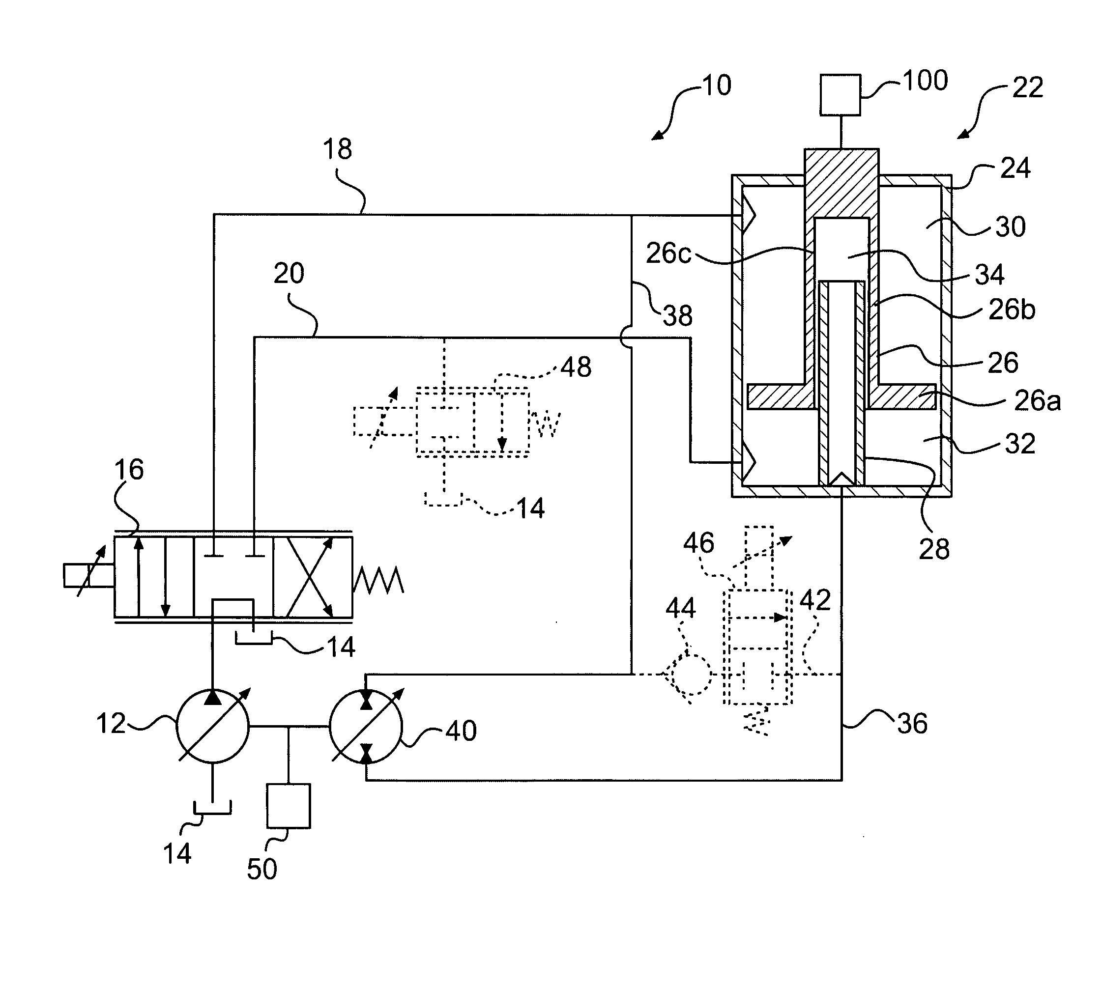
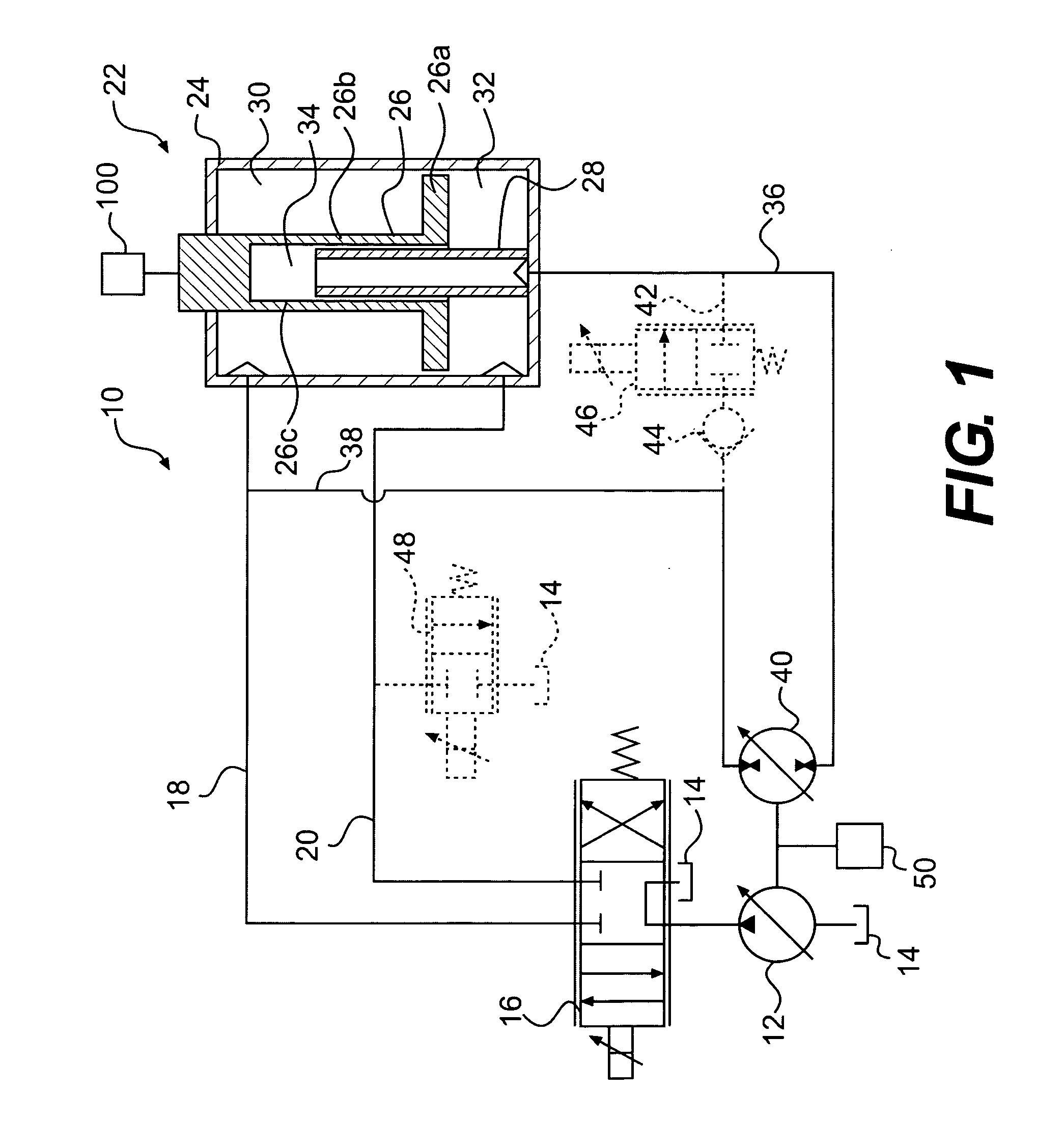
[0009]FIG. 1 illustrates an exemplary hydraulic system 10. Hydraulic system 10 may include a high pressure source 12, a low pressure source 14, a valve 16, an actuator 22, and a hydraulic motor 40. Hydraulic system 10 may also include one or more passageways fluidly interconnecting one or more components thereof. It is contemplated that hydraulic system 10 may include additional and / or different components such as, for example, pressure sensors, temperature sensors, position sensors, controllers, accumulators, relief valves, make-up valves, and / or other components known in the art.

[0010]High pressure source 12 may be configured to produce a flow of pressurized fluid and may include a pump such as, for example, a variable displacement pump, a fixed displacement pump, or any other source of pressurized fluid known in the art. High pressure source 12 may be drivably connected to a power source (not shown) by, for example, a countershaft (not shown), a belt (not shown), an electrical ci...


PUM

PropertyMeasurementUnit
Pressureaaaaaaaaaa
Volumeaaaaaaaaaa
Areaaaaaaaaaaa

Abstract

A hydraulic system is disclosed. The hydraulic system includes an actuator including a first, a second, and a third fluid chamber. The hydraulic system also includes a high pressure source of pressurized fluid in selective fluid communication with the first and second fluid chambers. The hydraulic system also includes a low pressure source of pressurized fluid in selective fluid communication with the first and second fluid chambers. The hydraulic system further includes a hydraulic motor in fluid communication with the third fluid chamber.

Description

TECHNICAL FIELD[0001]The present disclosure relates to hydraulic systems and, more particularly, to hydraulic systems with energy recovery.BACKGROUND[0002]Hydraulic systems often include one or more actuators configured to affect movement of an operatively connected load. Often machines include one or more such hydraulic systems to affect movement of one or more components, such as, for example, a frame member, a linkage, an implement, and / or other components. The hydraulic system usually includes a pump configured to supply pressurized fluid and a valve arrangement configured to direct pressurized fluid to and from an actuator. The actuator is often a piston-cylinder arrangement where the valve arrangement selectively supplies pressurized fluid to a first chamber therein and selectively drains pressurized fluid from a second chamber therein to affect movement of the piston with respect to the cylinder. Often the pressurized fluid drained from the actuator is directed toward a tank,...

Claims


Application Information

Patent Timeline
IPC IPC(8): F15B21/14F16D31/02F15B15/00F15B11/02F15B1/02
CPCF15B11/036F15B2211/88F15B21/14F15B2211/20546F15B2211/20561F15B2211/20569F15B2211/20592F15B2211/265F15B2211/3058F15B2211/327F15B2211/40515F15B2211/41527F15B2211/426F15B2211/45F15B2211/7055F15B2211/76F15B15/1466B29B7/283Y02P70/10
Inventor BRINKMAN, JASON L.
Owner CATERPILLAR INC
Why Eureka
Try Eureka