Particle separator using boundary layer control

Inactive Publication Date: 2008-07-03
GENERAL ELECTRIC CO
View PDF17 Cites 31 Cited by
  • Summary
  • Abstract
  • Description
  • Claims
  • Application Information

AI Technical Summary

Benefits of technology

[0011]a boundary layer control mechanism for providing active boundary layer con

Problems solved by technology

Aircraft gas turbine engines may be susceptible to damage from foreign objects introduced into air inlets of the engines.
With the advent of gas turbine powered helicopters and other vertical takeoff and landing (VTOL) aircraft, smaller particles of foreign matter such as sand and dust have become increasingly troublesome due primarily to the conditions under which such VTOL aircraft may be operated.
These foreign particles, which individually have relatively little effect on the engine, may cause very s

Method used


Image

  • Particle separator using boundary layer control
  • Particle separator using boundary layer control
  • Particle separator using boundary layer control

Examples


Embodiment Construction

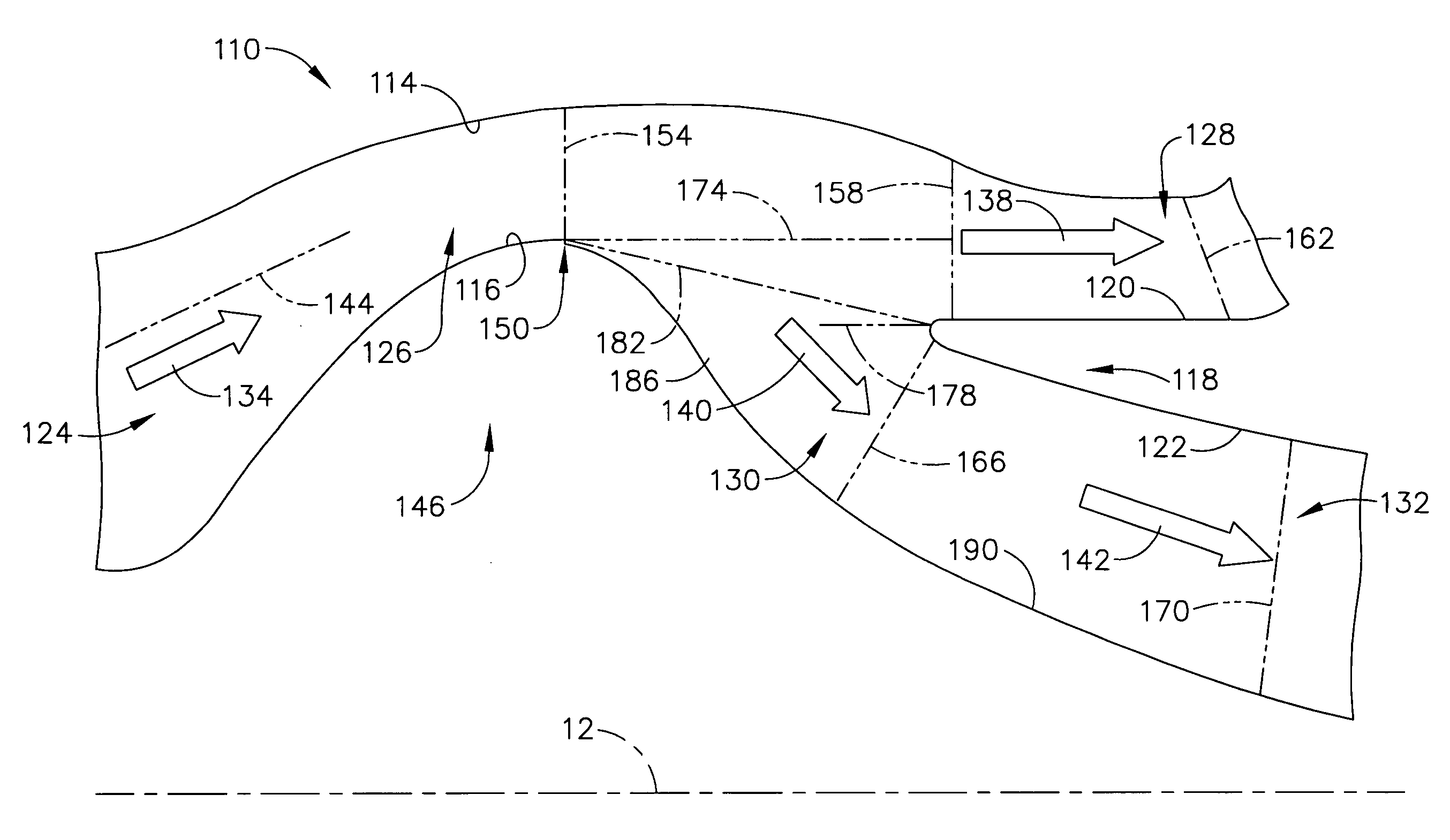
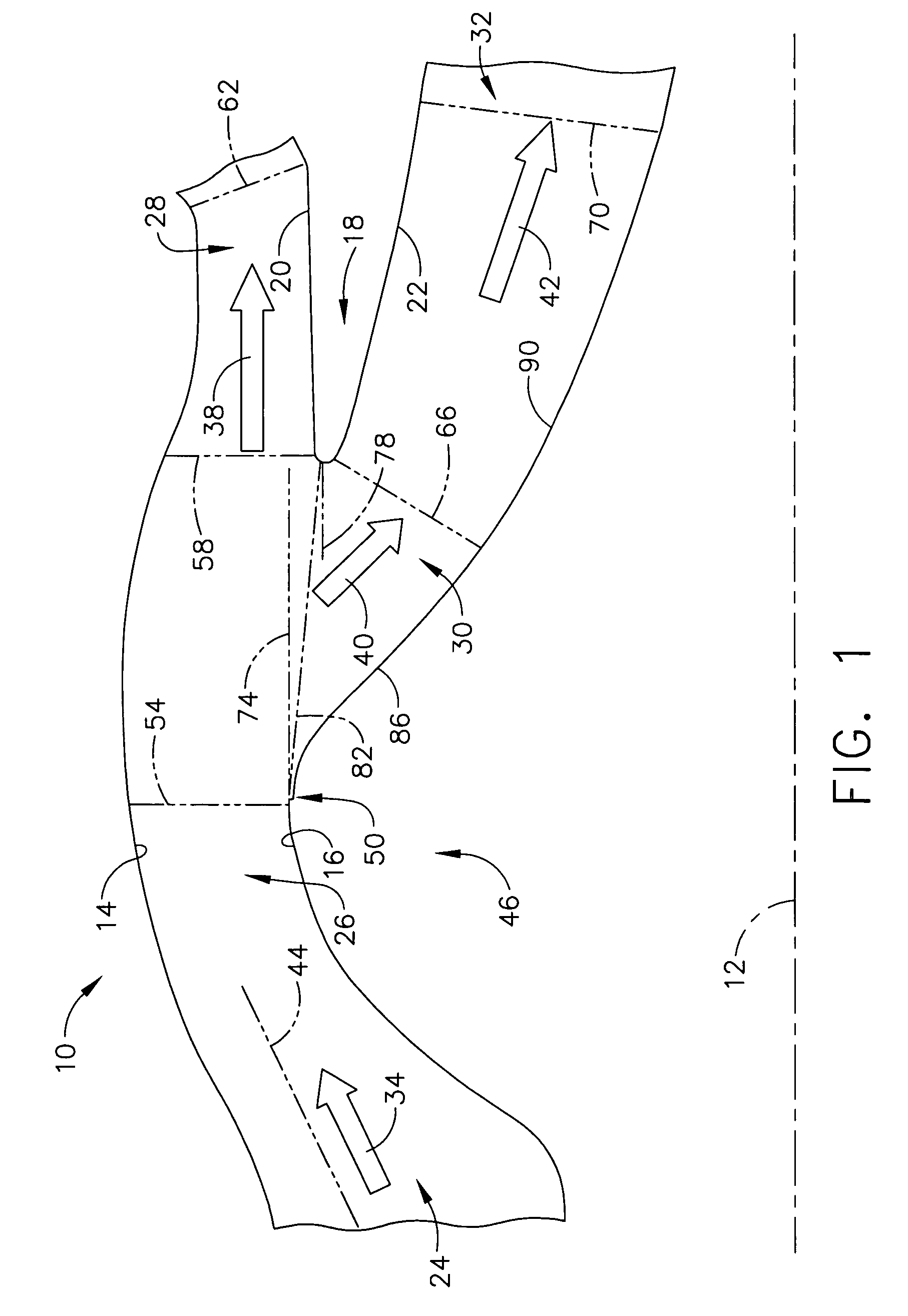
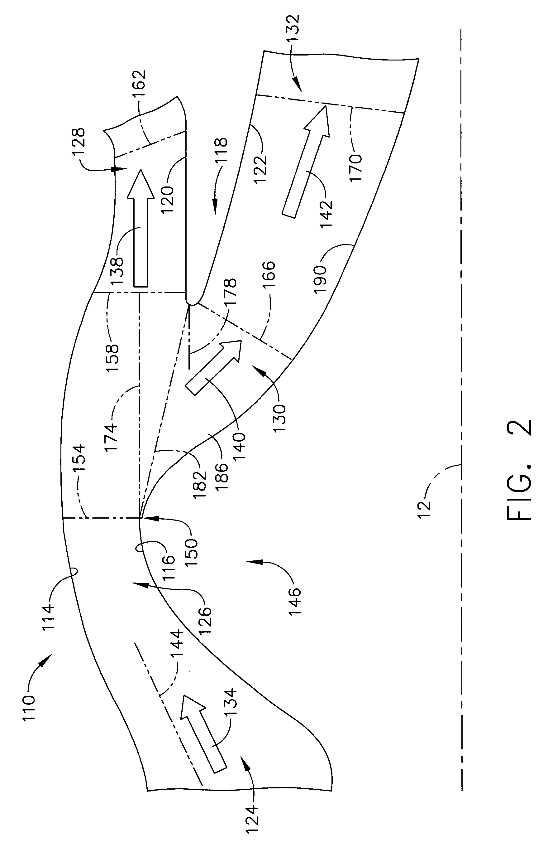
[0022]As used herein, the term “particle separator” refers to a device (e.g., inertial particle separator) for removing, for example, sand particles, dust particles, salt particles, etc., from an inlet air stream of, for example, a gas turbine engine, other type of engine, industrial device, etc.

[0023]As used herein, the term “splitter” (also known as a “splitter lip”) refers to a device for removing, separating, etc., various entrained foreign objects, for example, sand particles, dust particles, salt particles, etc., from the inlet air stream of, for example, a gas turbine engine, other type of engine, industrial device, etc., to provide a main or core air flow stream having a minimized, reduced, etc., level of such entrained foreign objects.

[0024]As used herein, the term “rain step” refers to a (e.g., a relatively small) recess, indentation, groove, etc., on the peak (i.e., maximum radius) of an inlet particle separator inner flowpath hump-shaped portion, and that is intended to ...


PUM

PropertyMeasurementUnit
Angleaaaaaaaaaa
Angleaaaaaaaaaa
Angleaaaaaaaaaa

Abstract

A particle separator which broadly comprises: an inner wall, an outer wall and a splitter, wherein the inner and outer walls define an air intake passageway, and wherein the splitter is positioned between the inner and outer walls so as to define a scavenge air flow passageway connected to the intake passageway and a main air flow passageway connected to the intake passageway; the inner wall having a humped-shaped portion between the intake passageway and the main air flow passageway; the humped-shaped portion having a peak and a radius of curvature at any point on the hump-shaped portion of the inner wall after the peak corresponding to a degree of curvature of from about 30 to about 60 degrees; and a boundary layer control mechanism for providing active boundary layer control along the inner wall after the peak and within the main air flow passageway. Also provided is a method for providing active boundary layer flow control along the inner wall after the peak and within the main air flow passageway.

Description

BACKGROUND OF THE INVENTION[0001]This invention broadly relates to a particle separator for a gas turbine engine providing for improved particle separation by increasing the splitter hiding height, decreasing the radius of curvature of the humped-shaped portion of the inner wall after the peak of the humped-shaped portion, and providing active boundary layer control along the inner wall after the peak and within the main air flow passageway. This invention further broadly relates to a method for providing such active boundary layer control along the inner wall after the peak and within the main air flow passageway.[0002]Aircraft gas turbine engines may be susceptible to damage from foreign objects introduced into air inlets of the engines. This problem has been most acute in the past with respect to relatively large foreign objects such as stones, gravel, birds and hail.[0003]With the advent of gas turbine powered helicopters and other vertical takeoff and landing (VTOL) aircraft, s...

Claims


Application Information

Patent Timeline
IPC IPC(8): B01D46/46
CPCF02C7/052Y02T50/675F05D2260/607F05D2270/17Y02T50/60
Inventor TINGLE, WALTER JACKSONOLIVER, WAYNE R.KIRTLEY, KEVIN RICHARD
Owner GENERAL ELECTRIC CO
Why Eureka
Try Eureka