Inhaler 624

a technology of inhaler and latch position, which is applied in the direction of operating means/release devices of valves, combustion types, lighting and heating apparatuses, etc., can solve the problems of mechanical failure of the inhaler, inability to deliver a dose of medicament after a number, and components of the trigger mechanism not being loaded, so as to achieve the effect of ensuring the latch position

Active Publication Date: 2008-07-03
ASTRAZENECA AB
View PDF6 Cites 113 Cited by
  • Summary
  • Abstract
  • Description
  • Claims
  • Application Information

AI Technical Summary

Benefits of technology

[0010]In this way, components of the trigger mechanism and finely toleranced parts are not loaded at any time, either when the inhaler is reset or discharged, except for when the actuator is armed and ready to deliver a dose of medicament. By avoiding heavy loading of the trigger mechanism, the onset of material creep is significantly reduced, resulting in an inhaler that may be re-used snore safely.
[0011]Preferably, the loading means further loads the canister with an actuation force for compression of the canister from a rest position to the charging position. Movement of the activating means to the first position applies a force directly to the loading means to compress the canister from the rest position to the charging position. By providing such an arrangement, the canister may be pre-compressed thus reducing the mechanical shock prior to the compressing of the canister to deliver a dose of medicament.
[0016]Preferably, the latch means comprises a trigger element and a droplink element, movement of the trigger element to its latch release position causes movement of the droplink element to its latch release position, thereby moving the lever lock from its lock position so a release position, causing the lever to move from its locked position to a release position thereby allowing compression of the canister to release a dose or medicament. The droplink element may further comprise a re-set position. This enables the droplink element to readily take up its latch position.

Problems solved by technology

Such an arrangement results in the components of the trigger mechanism not being loaded when the inhaler is not in use.
Over time, loading of critical components can quicken the onset of material creep, resulting in mechanical failure of the inhaler and its subsequent inability to deliver a dose of medicament after a number of uses.
This situation can be extremely dangerous for the user in an emergency when it is vital that the inhaler deliver a dose when required.

Method used


Image

  • Inhaler 624
  • Inhaler 624
  • Inhaler 624

Examples


Embodiment Construction

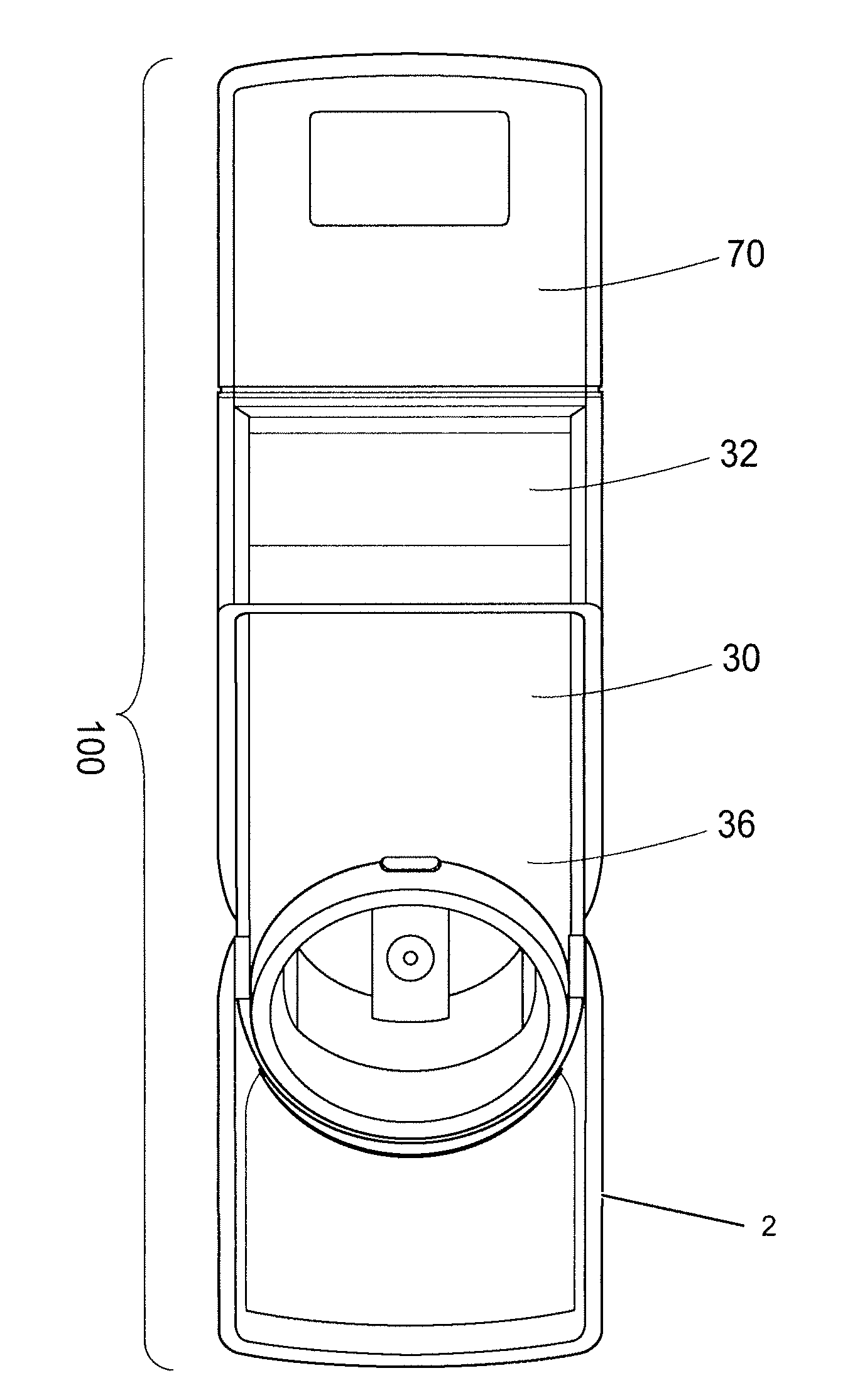
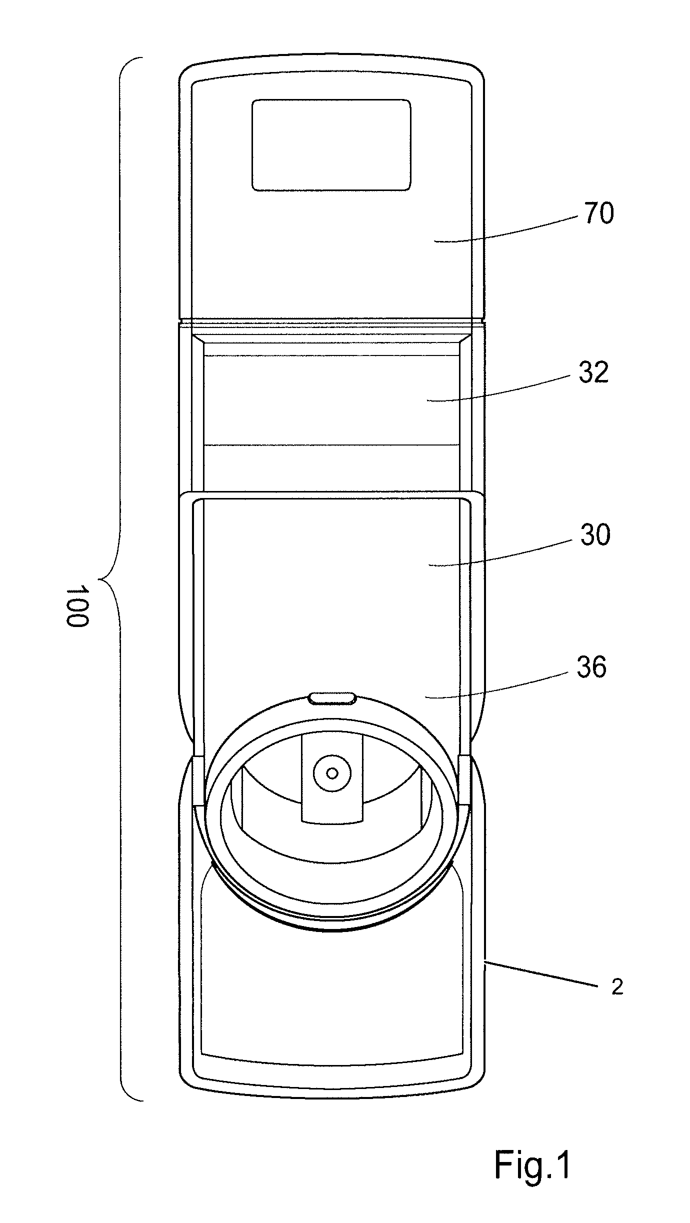
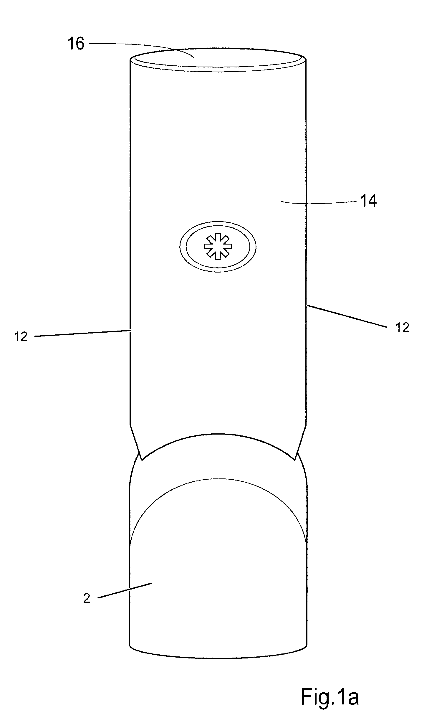
[0037]Referring now to FIGS. 1, 1a, 2 and 7, one embodiment of a breath actuated inhaler (BAI) actuator 100, with respect to this embodiment referred to as an inhaler 100, has a housing 10 comprising side walls 12, a rear wall 14 and a top wall 16. The rear wall 14 forms a curved surface to facilitate comfortable receipt of the inhaler 100 in the palm of the user's hand. The walls 12, 14, 16 of the housing 10 define a space for accommodating a canister 20 of medicament in a chassis 40, and an actuation mechanism 1 so operable as to actuate the canister 20 to deliver a dose of medicament. The chassis 40 retains most of the mechanical components of the inhaler 100 in the correct position, and is heavily loaded. For example, most of the components of the trigger mechanism are pivoted on the chassis 40, thus reducing problems caused by tolerance. The front opening in the housing 10 accommodates a registration module (electronic module) 70 and an upper portion 32 of a facia 30, each havi...


PUM


Abstract

The present invention relates to an Breath actuated inhaler (BAI) actuator, comprising: a loading element capable of being loaded with an actuation force, a breath actuated trigger mechanism arranged to counteract the actuation force of the loading element, and to fire the actuator by releasing the actuation force of the loading element in response to an inhalation breath, and actuation locking means moveable between a locked position wherein it relieves the actuation force from the trigger mechanism setting the trigger mechanism in a neutral position, and an armed position wherein the trigger mechanism is set in an armed position.

Description

RELATED APPLICATIONS[0001]Under 35 U.S.C. §119(e)(1), this application claims the benefit of prior U.S. provisional application 60 / 883,076, filed Jan. 2, 2007.TECHNICAL FIELD[0002]The present invention relates to an inhaler for delivery of a medicament by inhalation and in particular to the actuation mechanism used in the inhaler to actuate a canister to dispense a dose of medicament.BACKGROUND OF THE INVENTION[0003]Inhalers are commonly used for delivery of a wide range of medicaments. The inhaler holds a canister of medicament, the canister being actuated e.g. by compression to deliver a dose of medicament through a mouthpiece to a user. The inhaler may be provided with an actuation mechanism to actuate the canister automatically and thus dispense a dose of medicament. Some known actuation mechanisms are breath-actuated, so that they operate in response to inhalation by a user. This ensures that a dose of medicament dispensed on actuation of the canister is supplied whilst the use...

Claims


Application Information

Patent Timeline
Patent Type & Authority Applications(United States)
IPC IPC(8): A61M11/00
CPCA61M15/009A61M15/0091A61M2205/6072A61M15/0095A61M15/0026A61M15/007A61M15/008A61M2205/6081A61M15/0081A61M15/0096A61M15/00A61M15/0086A61M15/0025A61M15/0071
Inventor BOWMAN, NICHOLASFRUENSGAARD, JORGENRASMUSSEN, JORGEN FUNDERVILSTRUP, HENRIK HOUGAARDCHRISTENSEN, KELD SLOTH
Owner ASTRAZENECA AB
Why Eureka
Try Eureka