Pneumatic Tire

Inactive Publication Date: 2008-07-03
YOKOHAMA RUBBER CO LTD
View PDF4 Cites 19 Cited by
  • Summary
  • Abstract
  • Description
  • Claims
  • Application Information

AI Technical Summary

Benefits of technology

[0026]According to the pneumatic tire of the present invention, (1) the belt layer is reinforced by the first circumferential-direction reinforcing layer and the second circumferential-direction reinforcing layer. Such reinforcement leads to an advantage that the anti-wear-breakage performance of the circumferential-direction reinforcing layers improves compared to the case where the belt layer is reinforced by only the first circumferential-direction reinforcing layer. (2) The second circumferential-direction reinforcing layer is arranged so as to be interposed between the carcass layer and the inner-side cross belt (the cross belt positioned on the tire-radial direction inner side). Such arrangement reduces the movement of the second circumferential-direction reinforcing layer in the tire width direction during contact of the tire with the road surface, compared to the structure (see Patent Document 1) in which the second circumferential-direction reinforcing layer is the outermost layer of the belt layer (the outermost layer in the tire radial direction). Accordingly, the separation near the second circumferential-direction reinforcing layer is reduced. This leads to an advantage that the anti-belt-edge separation performance of the tire improves. Especially, (3) the edge of the first circumferential-direction reinforcing layer on the tire-width direction outer s

Problems solved by technology

As a result, separation

Method used


Image

  • Pneumatic Tire
  • Pneumatic Tire
  • Pneumatic Tire

Examples


embodiment

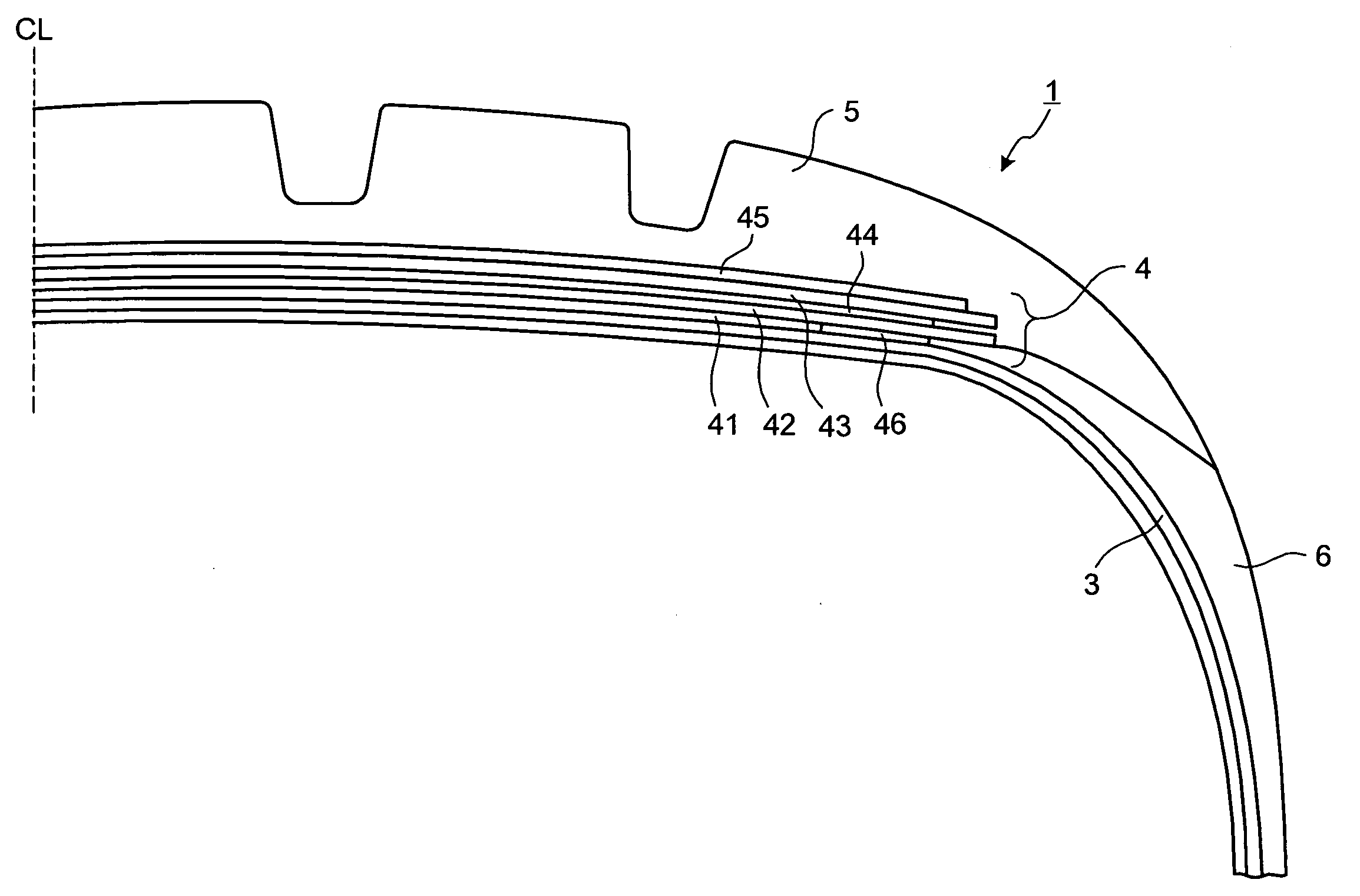
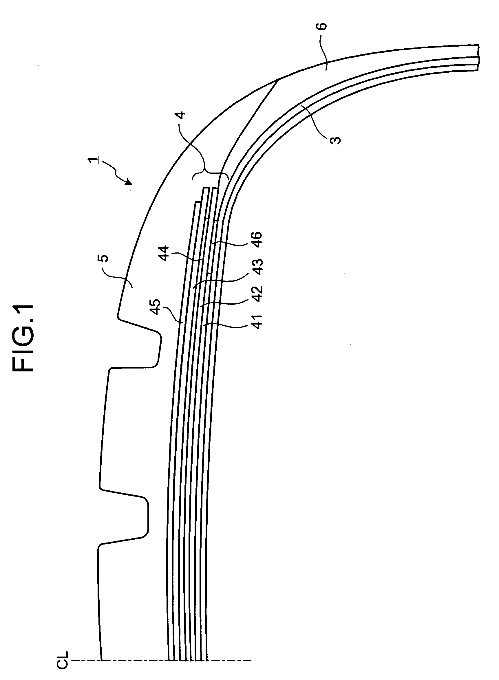
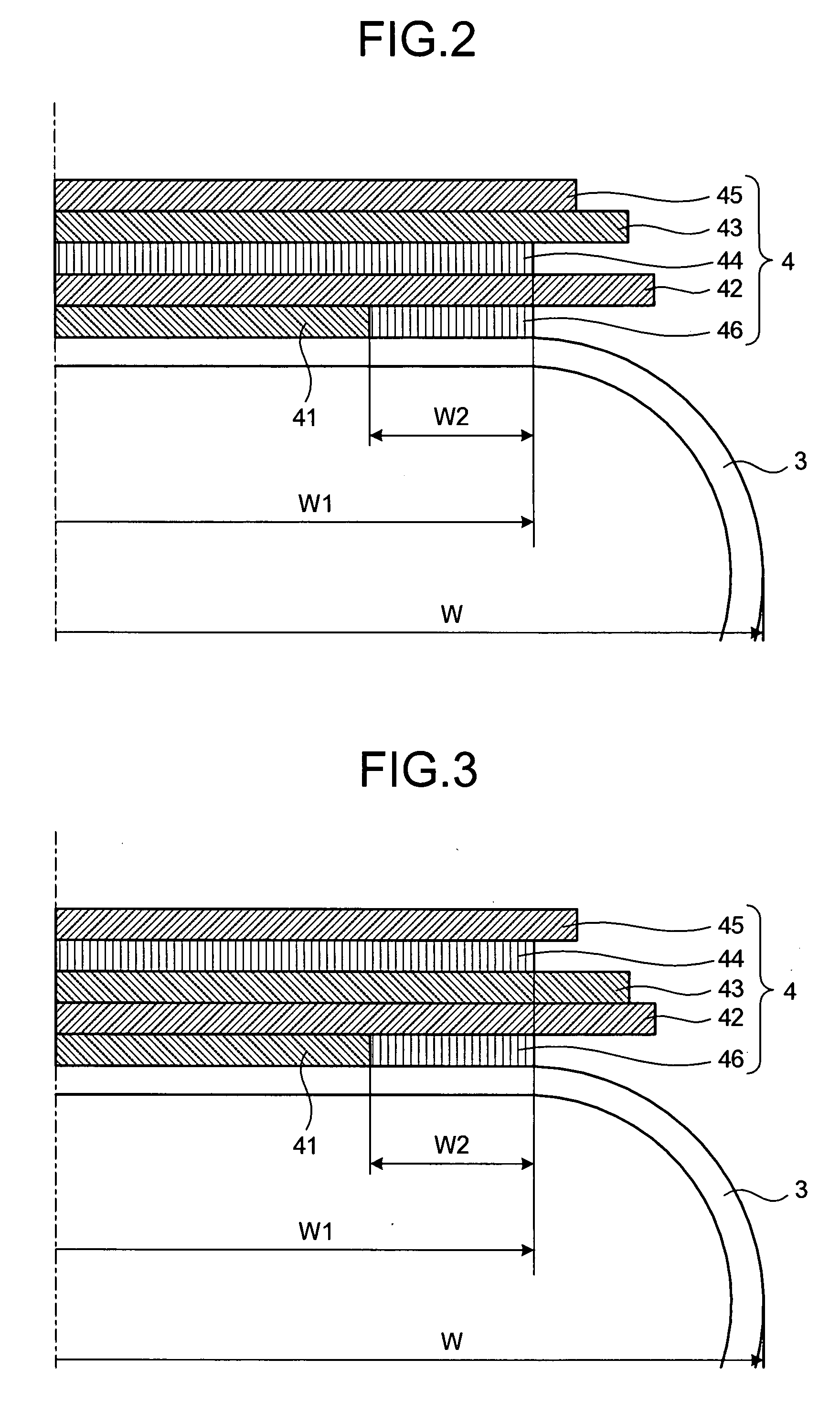
[0050]FIG. 1 is a cross section a pneumatic tire in a tire meridian direction according to an embodiment of the present invention. FIG. 2 is an explanatory view of a belt structure of the pneumatic tire shown in FIG. 1. FIG. 3 is an explanatory view of a modified example of the pneumatic tire shown in FIG. 1. FIGS. 4 to 11 are tables each containing results of performance tests of pneumatic tires.

[0051]A pneumatic tire 1 includes bead cores (not shown), a carcass layer 3, a belt layer 4, tread rubber 5, and side wall rubbers 6 (see FIG. 1). A bead core is provided on the left and the right. The carcass layer 3 extends between the left and right bead cores, and it has a toroidal shape. The belt layer 4 is formed of a plurality of belt members of 41 to 46 that are superposed, and is arranged on a tire-radial direction outer side with respect to the carcass layer 3. The tread rubber 5 is arranged on the tire-radial direction outer side with respect to both the carcass layer 3 and the b...

first modified example

[0061]In the pneumatic tire 1, the first circumferential-direction reinforcing layer 44 is arranged so as to be interposed between the cross belts 42 and 43. However, the arrangement of the first circumferential-direction reinforcing layer 44 is not limited to this arrangement. The first circumferential-direction reinforcing layer 44 can be arranged so as to be interposed between the outer-side cross belt 43 and the protection belt 45 (see FIG. 3). With such a structure, the above functions and effects of (1) to (3) are obtained. Because the movement of the first circumferential-direction reinforcing layer 44 is constrained because of the protection belt 45, the separation near the first circumferential-direction reinforcing layer 44 is suppressed. Such suppression of separation leads to an advantage that the anti-belt-edge-separation performance of the tire improves.

[0062]In the above structure, it is preferable that the cord member of the protection belt 45 be oblique in a directi...

second modified example

[0063]In the pneumatic tire 1, it is preferable that each cord member of each of the cross belts 42 and 43 has a fiber direction oblique to the tire circumferential direction at an angle of 25 degrees or smaller. Such an angle leads to an advantage that the tire radial growth is effectively suppressed during application of a load due to internal pressure.

[0064]It is preferable that the cord member of the high-angle belt 41 has a fiber direction oblique to the tire circumferential direction at an angle of 60 degrees or larger. Especially, if the cords of the cross belts 42 and 43 have fiber directions oblique to the tire circumferential direction at small angles (for example, 25 degrees or smaller), the rigidity to the tire circumferential direction in the tire cross-sectional direction is low. Hence, the anti-wear-breakage performance and shock resistance of the carcass layer 3 may deteriorate. For this reason, the high-angle belt 41 having the above structure leads to an advantage ...


PUM


Abstract

In a pneumatic tire, a belt layer includes six superposed belt members. The edge of the fourth belt member on the tire-width direction outer side and the edge of the sixth belt member on the tire-width direction outer side are at approximately the same position in a tire width direction.

Description

TECHNICAL FIELD[0001]The present invention relates to a pneumatic tire. The present invention relates more specifically to a pneumatic tire having a suppressed radial growth during application of a load due to internal pressure in addition to improved anti-belt-edge-separation performance.BACKGROUND ART[0002]In a tire for trucks or busses with an aspect ratio of 60% or smaller, a large load is applied to the belt layer of the tire due to internal pressure. Accordingly, a fastening effect with which the tire radial growth is suppressed decreases, and thus, deformation increases. As a result, separation tends to occur easily. For this reason, there is need to improve anti-belt-edge-separation performance and suppress tire radial growth of the tires for trucks or busses.[0003]A conventional pneumatic tire that satisfies the above need is disclosed in Patent Document 1. The conventional pneumatic tire P includes a radial carcass reinforcement, on which a crown reinforcing member is plac...

Claims


Application Information

Patent Timeline
IPC IPC(8): B60C9/18
CPCB60C9/2006Y10T152/10765Y10T152/10783Y10T152/10801B60C2009/2219B60C2200/06
Inventor ISOBE, SATORU
Owner YOKOHAMA RUBBER CO LTD
Why Eureka
Try Eureka