Non-backed-up packing element system

a packing element and non-backed-up technology, applied in the direction of sealing/packing, fluid removal, borehole/well accessories, etc., can solve the problems of increasing the cost of running and setting these prior packing element systems, and achieve the effect of effective sealing a casing string, less axial loading, and reduced cos

Inactive Publication Date: 2008-07-03
BAKER HUGHES INC
View PDF2 Cites 12 Cited by
  • Summary
  • Abstract
  • Description
  • Claims
  • Application Information

AI Technical Summary

Benefits of technology

[0007]The cantilever element and ramp element are disposed adjacent to each other at an angle less than 90 degrees and, preferably, greater than about 45 degrees. In a particularly preferred embodiment, the angle is in the range from 45 to 60 degrees, and more preferably at 50 degrees. The inclusion of a cantilever element and ramp element disposed adjacent and relative to each other at these angles allows the packing element system to effectively seal a casing string against the inner wall surface of a wellbore casing without the need for a back-up component.
[0008]The packing element systems and methods of setting a packing element system in a wellbore may have one or more of the following advantages: not requiring a back-up element; decreasing the costs associated with the manufacture, running-in, and milling out of the packing element systems; permitting setting of the packing element system with less axial loading; providing shortened manufacturing time; providing shortened mill time; not requiring specialized components such as a Teflon(& barrier; and reducing the length of prior packing element systems.

Problems solved by technology

These shortcomings result in increased costs associated with running and setting these prior packing element systems.

Method used


Image

  • Non-backed-up packing element system
  • Non-backed-up packing element system
  • Non-backed-up packing element system

Examples


Embodiment Construction

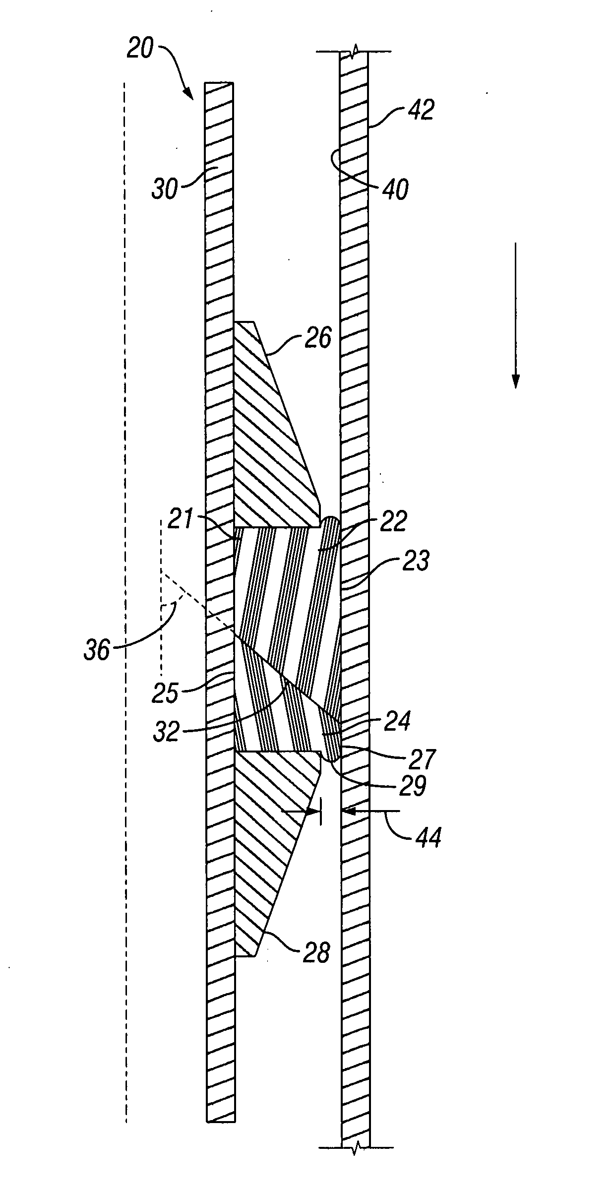
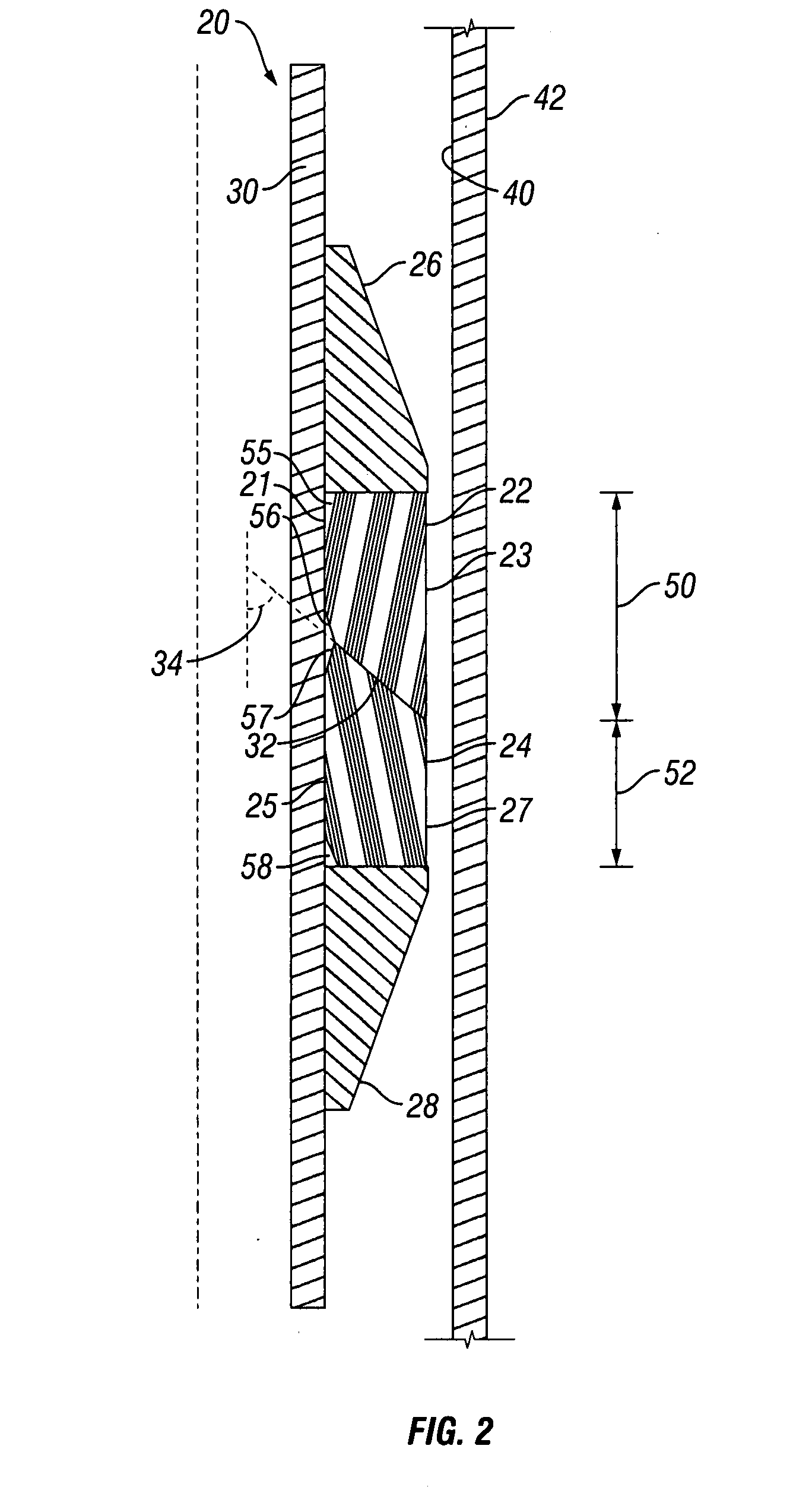
[0023]Referring now to FIGS. 2-3, packing element system 20 is shown in its initial or run-in position (FIG. 2) and its set position (FIG. 3). Broadly, packing element system 20 includes five components or parts: cantilever element 22, ramp element 24, upper cone 26, and lower cone 28, all carried on mandrel 30. Cantilever element 22, ramp element 24, upper cone 26, and lower cone 28 are tubular members, each having an inner surface determined by an inner diameter that receives mandrel 30. As will be appreciated by persons of ordinary skill in the art, mandrel 30 is a tubular member carried on a casing string (not shown). Mandrel 30 can be secured to the casing string through any device or method known to persons of ordinary skill in the art. No back-up component such as component 15 shown in FIG. 1 is required.

[0024]Cantilever element 22 is a deformable element formed from a deformable material that is in contact with ramp element 24 at interface 32. Ramp element 24 also is a defor...


PUM


Abstract

Well tool packing element systems that do not require a back-up element or component include a mandrel, an upper supporting member, a lower supporting member, a cantilever element, and a ramp element disposed on the mandrel. The cantilever element and ramp element are disposed on the mandrel with an interface angle between the cantilever element and the ramp element, the interface angle being less than 90 degrees, preferably in a range from 40 degrees to 60 degrees, and more preferably at an angle greater than 45 degrees. When an axial load is applied to upper and lower supporting members, cantilever element and ramp element are forced outward and into an inner wall surface of a casing to seal off the casing bore.

Description

BACKGROUND[0001]1. Field of Invention[0002]The invention is directed to packing element systems for use in a casing string in a wellbore and, in particular, to packing element systems lacking a back-up component.[0003]2. Description of Art[0004]Referring to FIG. 1, prior packing element systems 10 include a housing or mandrel 11 with a packing element 12 disposed therein. Each end of packing element 12 includes housing or support 13 to facilitate elastic expansion of packing element 12 away from mandrel 11 when an axial load is placed on packing element 12 at axial load points 14. Each end of packing element 12 also includes two back-up elements 15, 16 each of which are shown as metal petal back-ups having bottom layer 17 and top layer 18, or a phenolic back-up (not shown), both of which are known in the art. Such prior packing element systems, comprising of a back-up element 15, have the shortcomings of increased manufacturing time, increased time to mill through the packing elemen...

Claims


Application Information

Patent Timeline
Patent Type & Authority Applications(United States)
IPC IPC(8): E21B33/12
CPCE21B33/1208E21B33/128
Inventor VINSON, JUSTIN P.KROLL, DENNIS E.BISHOP, DAVID S.CLARK, KEVIN W.
Owner BAKER HUGHES INC
Why Eureka
Try Eureka