Method for reducing occurrences of tape stick conditions in magnetic tape

a technology of magnetic tape and occurrences, which is applied in the direction of moving record carriers backward/forward, mechanical tension control of carriers, instruments, etc., can solve the problems of tape sticking or breaking, tape sticking or falling, and the tendency of the drive to drop tension, so as to reduce the occurrence of tape stick conditions, and the effect of dropping tension

Inactive Publication Date: 2008-07-03
GOOGLE LLC
View PDF16 Cites 3 Cited by
  • Summary
  • Abstract
  • Description
  • Claims
  • Application Information

AI Technical Summary

Benefits of technology

[0006]Disclosed is a method for reducing occurrences of tape stick conditions in magnetic tape, the method including stopping functional rotation of each of a bi-directionally rotatable supply reel and a bi-directionally rotatable take-up reel of a reel-to-reel tape drive that includes a length of magnetic tape at least partially wound around each of the reels, a portion of the length of tape extending between the reels and contacting a head positioned between the reels, wherein the stopping creates a stop condition in the tape drive, determining if the length of tape is stuck to the head, dropping tension in the length of tape extending between the reels from full tension to zero tension, freeing the length of tape for movement in a z-direction relative to the head via the dropping tension, the z-direction running substantially parallel to a deck of the tape drive and substantially orthogonal to the length of tape, moving the head in y-directions relative to the length of tape wherein the y-directions includes movement substantially toward and away from the deck of the tape drive, moving the length of tape in an x-direction relative to the head via a rotation of the bi-directionally rotatable supply reel a fraction of a reel rotation during the stop condition, and causing the portion of the length of tape to at least temporarily break contact with the head via at least one of the dropping, the moving of the length of tape in the z-direction, the moving of the length of tape in the x-direction, and the moving of the head in the y-directions.
[0007]Also disclosed is a method for reducing occurrences of tape stick conditions in magnetic tape, the method including stopping functional rotation of each of a bi-directionally rotatable supply reel and a bi-directionally rotatable take-up reel of a reel-to-reel tape drive that includes a length of magnetic tape at least partially wound around each of the reels, a portion of the length of tape extending between the reels and contacting a head positioned between the reels, wherein the stopping creates a stop condition in the tape drive, determining if the length of tape is stuck to the head, dropping tension in the length of tape extending between the reels from full tension to zero tension, freeing the length of tape for movement in a z-direction relative to head, the z-direction running substantially parallel to a deck of the tape drive and substantially orthogonal to the length of tape, moving the head in y-directions relative to the length of tape wherein the y-directions includes movement substantially toward and away from the deck of the tape drive, moving the length of tape in an x-direction relative to the head via a rotation of the bi-directionally rotatable supply reel a fraction of a reel rotation during the stop condition; and re-determining if the length of tape is stuck to the head.

Problems solved by technology

Smoother media leads to more frequent occurrences of adherence between the tape and magnetic heads of the drives, especially in humid conditions.
Once the tape sticks to the head, the drive tends to drop tension because it cannot move the tape.
This leaves the drive with stuck or broken tape, which is an extremely undesirable condition to a user.
Once stuck to the head, the risk to breaking the tape is very high.

Method used


Image

  • Method for reducing occurrences of tape stick conditions in magnetic tape
  • Method for reducing occurrences of tape stick conditions in magnetic tape
  • Method for reducing occurrences of tape stick conditions in magnetic tape

Examples


Embodiment Construction

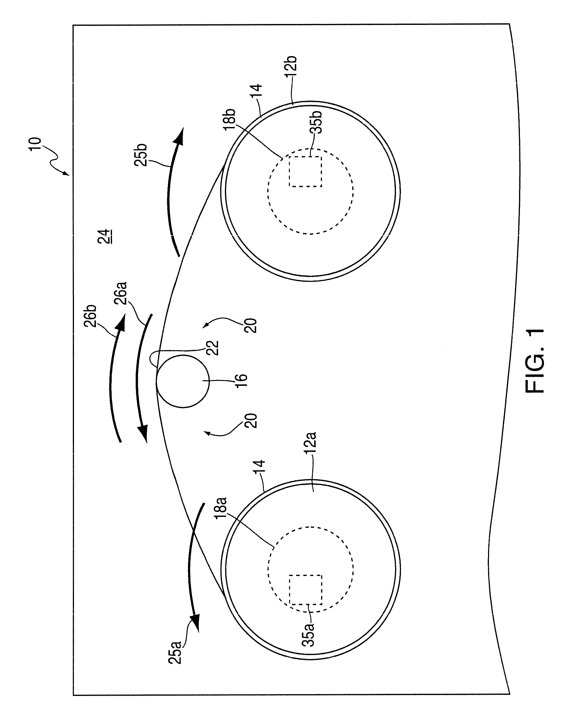
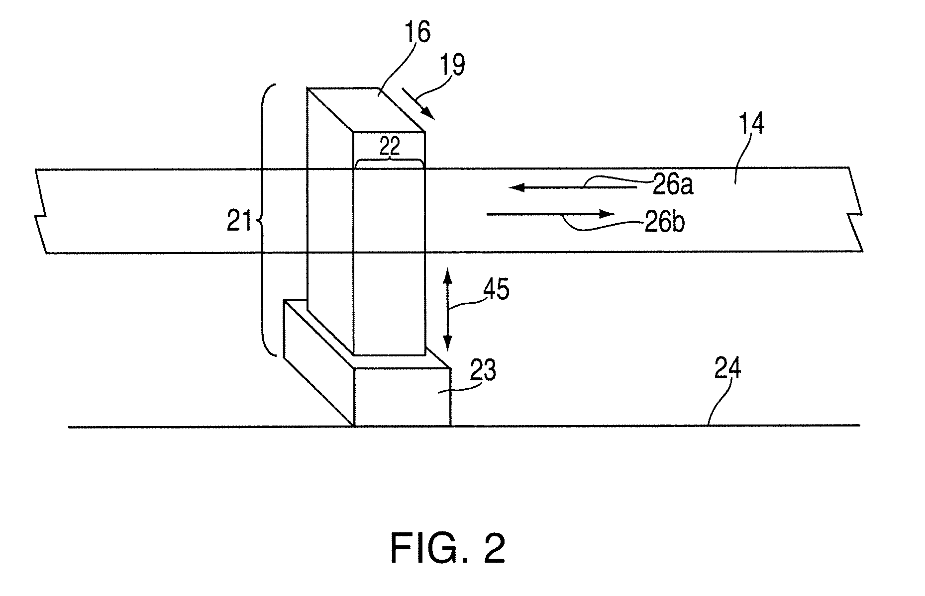
[0013]Referring to FIGS. 1 and 2, there is shown a reel-to-reel tape drive 10. The tape drive 10 includes a bi-directionally rotatable supply reel 12a, a bi-directionally rotatable take-up reel 12b, a length of magnetic tape 14, a head 16, and two motors 18a-b. The head 16 is disposed in a head region 20 between the two reels 12a-b. A portion 22 of the length of tape 14 consistently extends between the reels 12a-b across the head region 20. This portion 22 may be any portion of the length of tape 14, with the portion 22 illustrated in FIG. 1 representing a portion that extends across the region 20 while the drive 10 is experiencing a stop condition (described in greater detail later in the disclosure). The portion 22 contacts the head 16 within the head region 20. During operation of the drive 10, the head 16 reads / writes on the tape via this contact.

[0014]Typically, drives experience two general conditions; operating conditions and stop conditions. Operating conditions include func...


PUM

PropertyMeasurementUnit
lengthaaaaaaaaaa
timeaaaaaaaaaa
electrical currentaaaaaaaaaa

Abstract

Disclosed is a method for reducing occurrences of stick conditions in tape, the method including stopping rotation of a supply reel and take-up reel of a drive that includes a length of tape, a portion of the tape extending between the reels and contacting a head between the reels, wherein the stopping creates a stop condition in the drive, determining if the tape is stuck to the head, dropping tension in the tape between the reels, freeing the tape for movement in a z-direction via the dropping tension, moving the head in y-directions, moving the tape in an x-direction via a rotation of the supply reel a fraction of a rotation, and causing the tape to break contact with the head via the dropping, moving of the tape in the z-direction, moving of the tape in the x-direction, and / or moving of the head in the y-directions.

Description

BACKGROUND OF THE INVENTION[0001]1. Field of the Invention[0002]The disclosure relates generally to a method for reducing occurrences of tape stick conditions in magnetic tape, and more particularly to a method for reducing occurrences of tape stick conditions in magnetic tape disposed in a reel-to-reel tape drive.[0003]2. Description of Background[0004]As linear and track densities are increased for magnetic tape in reel-to-reel tape drives, it becomes desirable to have smoother and smoother media. Smoother media leads to more frequent occurrences of adherence between the tape and magnetic heads of the drives, especially in humid conditions. This is caused by the “Jo-block” effect, wherein two smooth surfaces are rubbed against each other squeezing out any lubricating air interface and causing the two smooth surfaces to stick.[0005]Once the tape sticks to the head, the drive tends to drop tension because it cannot move the tape. This leaves the drive with stuck or broken tape, whic...

Claims


Application Information

Patent Timeline
Patent Type & Authority Applications(United States)
IPC IPC(8): G11B15/48
CPCG11B15/1808G11B15/64G11B15/43G11B15/20
Inventor BAYANG, JOSEPHINE F.BUI, NHAN X.GALE, ERNEST S.OGURA, EIJITSURUTA, KAZUHIRO
Owner GOOGLE LLC
Why Eureka
Try Eureka