Anti-tip assembly for a power wheelchair

Inactive Publication Date: 2008-07-03
MERITS HEALTH PRODS
View PDF6 Cites 42 Cited by
  • Summary
  • Abstract
  • Description
  • Claims
  • Application Information

AI Technical Summary

Benefits of technology

[0011]The main objective of the present invention is to provide an anti-tip

Problems solved by technology

When the mounting frame (731) of the front wheel device (73) is heavy and stiff, the power wheelchair (70) provides an uncomfortable ride on rugged and rough ground and cannot traverse obstacles easily.
A light and flexible mou

Method used


Image

  • Anti-tip assembly for a power wheelchair
  • Anti-tip assembly for a power wheelchair
  • Anti-tip assembly for a power wheelchair

Examples


Example

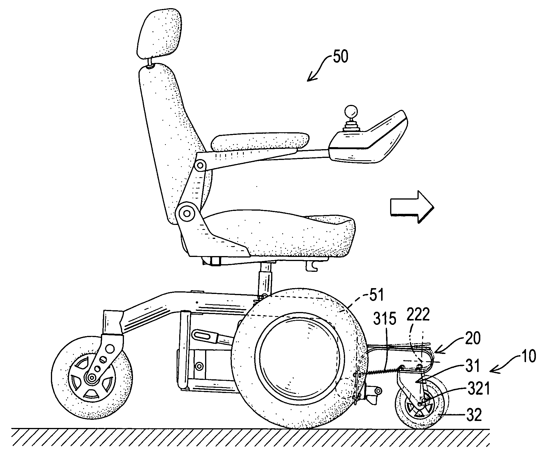
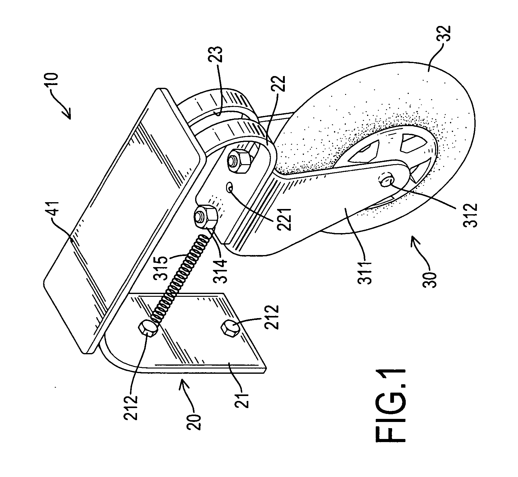
[0022]With reference to FIGS. 1 to 3, an anti-tip assembly (10) in accordance with the present invention for a power wheelchair (50) with a frame (51) is connected to the frame (51) of the power wheelchair (50) and has a resilient bracket (20), a front wheel assembly (30) and an optional footrest (40).

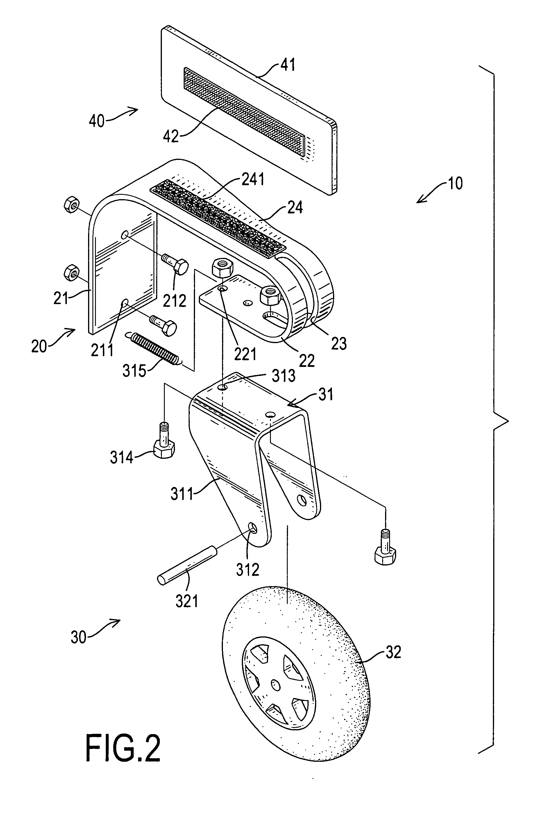
[0023]The resilient bracket (20) may be L-shaped, is connected securely to the frame (51) of the power wheelchair (50) and has a mounting bracket (21), a resilient arm (24) and a resilient wheel connector (22).

[0024]The mounting bracket (21) is connected to the frame (51) of the power wheelchair (50) and has a top edge, multiple optional mounting holes (211) and multiple optional fasteners (212). The mounting holes (211) are formed through the mounting bracket (21). The fasteners (212) extend respectively through the mounting holes (211), connect the mounting bracket (21) to the frame (51) and may be bolts.

[0025]The resilient arm (24) is formed on and protrudes forward from the top edg...


PUM


Abstract

An anti-tip assembly for a power wheelchair with a frame and has a resilient bracket and a front wheel assembly. The resilient bracket has a mounting bracket, a resilient arm and a resilient wheel connector. The mounting bracket is connected to the frame and has a top edge. The resilient arm is formed on and protrudes forward from the top edge of the mounting bracket and has a distal end. The resilient wheel connector is formed on and extends from the distal end of the resilient arm and has a bottom leg. The front wheel assembly is connected securely to the bottom leg of the resilient wheel connector and has a wheel bracket and an idler wheel. The wheel bracket is connected to the bottom leg of the resilient wheel connector and has two wings. The idler wheel is mounted rotatably between the wings.

Description

BACKGROUND OF THE INVENTION[0001]1. Field of the Invention[0002]The present invention relates to an anti-tip assembly, and more particularly to an anti-tip assembly used on a power wheelchair.[0003]2. Description of Related Art[0004]With reference to FIG. 8, a conventional power wheelchair (70) has a frame (701), a motor, two drive wheels (71), two rear wheels (72) and two front wheel devices (73). The frame (701) has a top, a front end, a rear end and a seat. The seat is mounted on the top of the frame to hold a person. The motor is mounted on the frame (701) below the seat. The drive wheels (71) are connected rotatably to the frame (701) below the seat and are driven by the motor. The rear wheels (72) are connected pivotally and rotatably to the rear end of the frame (701). The front wheel devices (73) are connected rotatably to and protrude from the front end of the frame (701), and each front wheel device (73) has a mounting arm (731), an idler wheel (732) and an axle (733).[000...

Claims


Application Information

Patent Timeline
IPC IPC(8): A61G5/10A61G5/04
CPCA61G5/042A61G2005/128A61G2005/1089A61G5/06A61G5/1089A61G5/128
Inventor CHENG, MING-CHUAN
Owner MERITS HEALTH PRODS
Why Eureka
Try Eureka