Network camera holder

a camera and network technology, applied in the field of network camera holders, can solve the problems of inability to interchange, high cost, and difficulty in adjusting the angle of the camera, and achieve the effect of facilitating the user to adjust the camera angl

Inactive Publication Date: 2008-07-03
LIANG HUI HU
View PDF4 Cites 16 Cited by
  • Summary
  • Abstract
  • Description
  • Claims
  • Application Information

AI Technical Summary

Benefits of technology

[0008]2. When the user desires to place the network camera on a desktop, the camera is secured to the longer arm of the L-shaped holder and the flushed surface of the shorter arm is placed on the desktop to facilitate the user to adjust the angle of the camera.

Problems solved by technology

Whereas a network camera generally available in the market is either placed on desktop or hooked upon a monitor, both positions are not interchangeable to limit the operation of the camera by its user.
Even the prior art allows the camera to be secured in both positions as desired, the construction and erection of its holder are comparatively complicate and involve higher cost, and even more complicate in case of a construction that allows adjustable angle.

Method used


Image

  • Network camera holder
  • Network camera holder
  • Network camera holder

Examples


Embodiment Construction

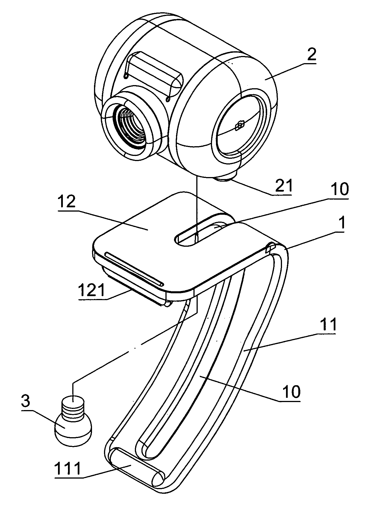
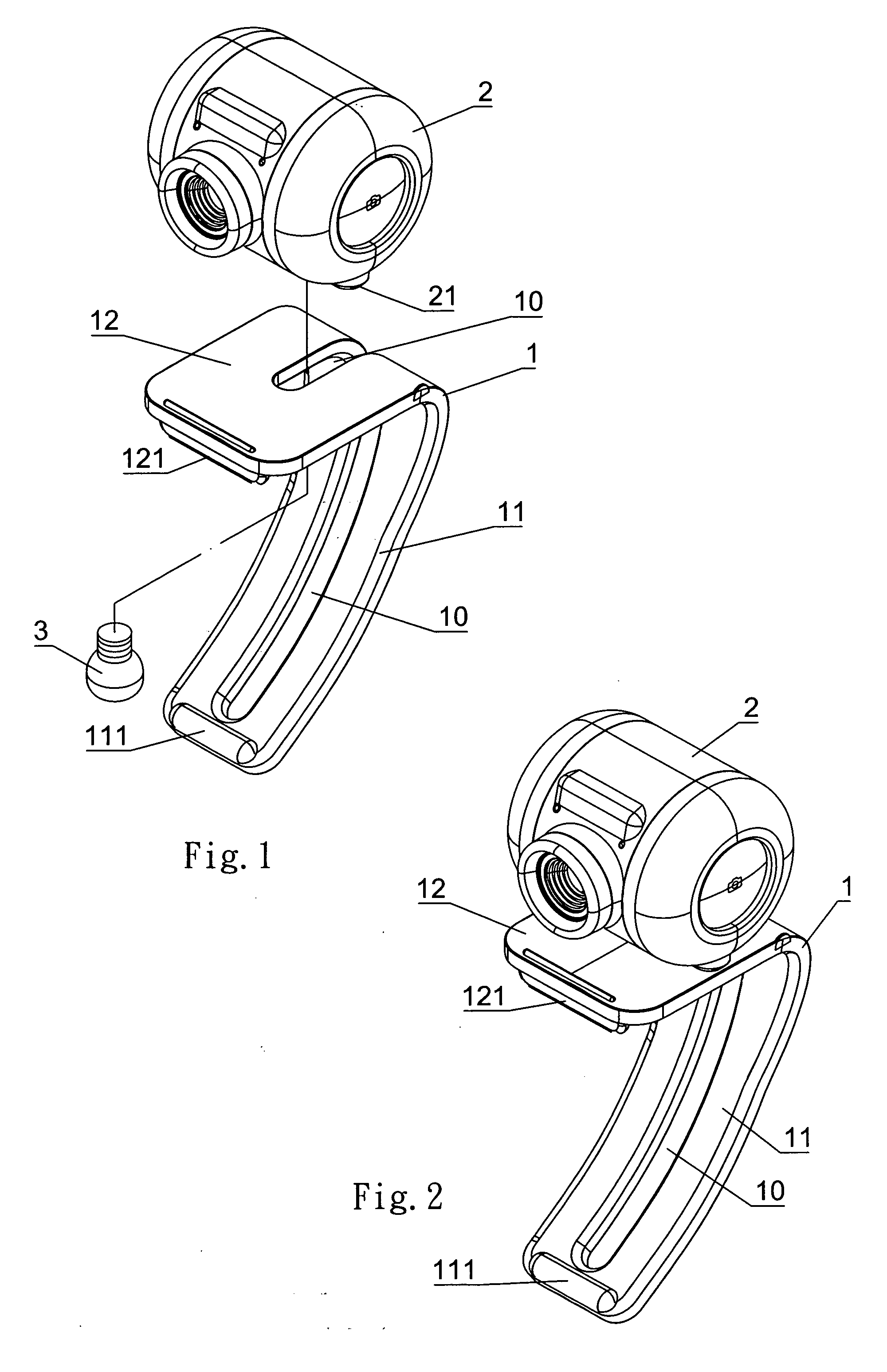
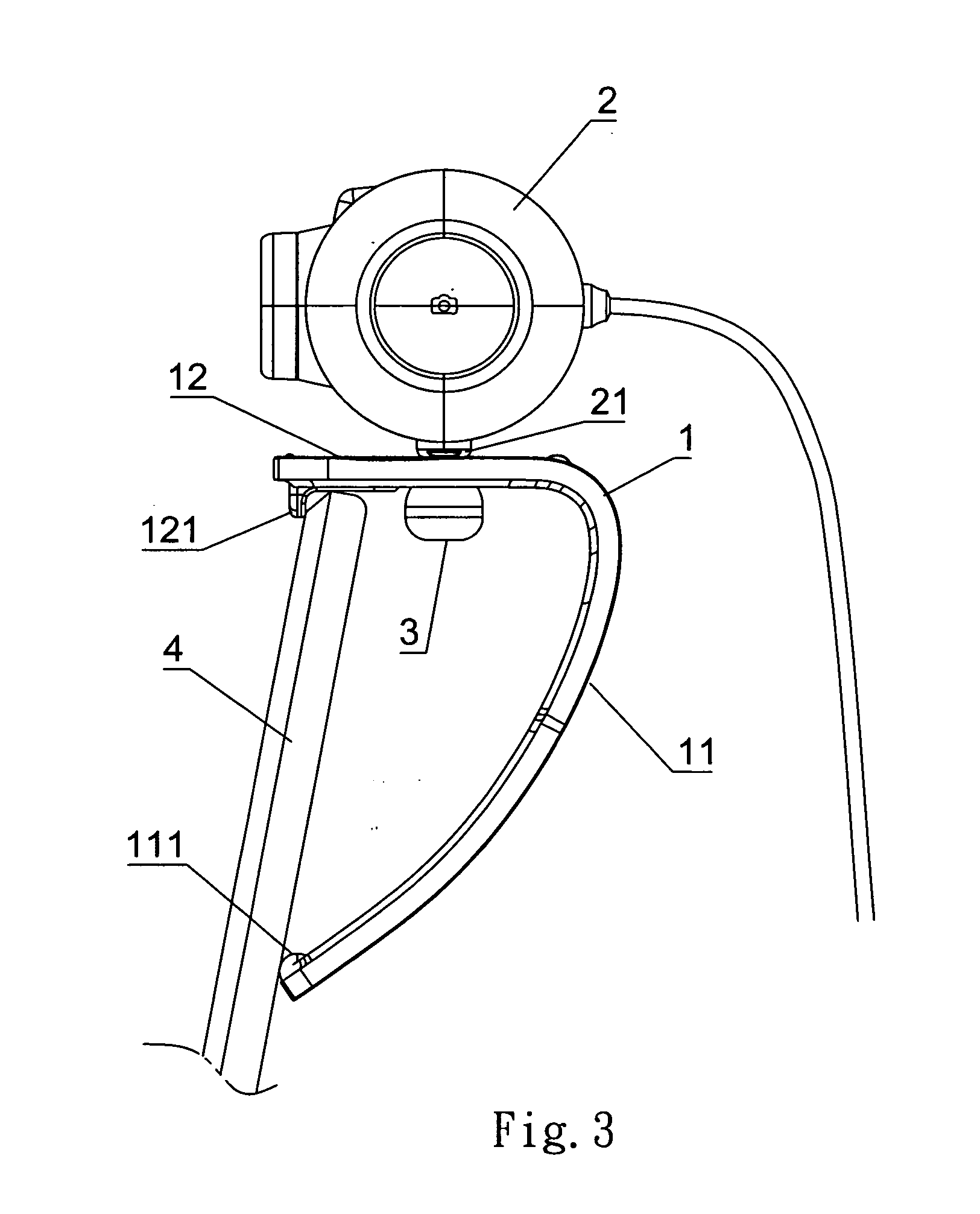
[0015]Referring to FIGS. 1, 2, and 3, an L-shaped holder 1 is longitudinally disposed at its central line an L-shaped slot 10. The L-shaped holder 1 is comprised of a longer arm 11 and a shorter arm 12. The longer arm 11 indicates a concave surface and the shorter arm 12 indicates a flushed surface. A retainer 121 is disposed on the inner side of the front end of the shorter arm 12 and a flange 111 is disposed on the inner side of the front end of the longer arm 11. A bolt 3 passes through the L-shaped slot 10 and locked in a screw hole 21 disposed at where below a network camera 2 for the camera 2 to move in the L-shaped 10 to a proper location to be secured in position by tightening up the bolt 3. Accordingly, by loosening the bolt to allow the camera 2 moving within the L-shaped slot 10, the camera 2 can be secured in a position as desired depending whether the L-shaped holder 1 to be placed on desktop as illustrated in FIG. 4 or hooked upon the upper edge of a monitor 4 as illus...


PUM


Abstract

A network camera holder includes an L-shaped holder provided along its central line an L-shaped slot; the holder comprised of a longer arm and a shorter arm; the longer arm having a concaved surface and the longer arm having a flushed surface; a retainer and a flange being respectively disposed on the inner side of the front end of the shorter arm and the longer arm; a screw hole being disposed on the lower end of the camera; a bolt passing through the L-shaped slot and locked in the screw hole; by loosening up the bolt to allow the camera to slide within the L-shaped slot to a proper location before being tightened up; when the camera being secured to the shorter arm, the camera being hooked to an upper edge of a monitor by the retainer while the flange from the longer arm holding against the back of a monitor; and when the camera being secured to the longer arm, the camera being placed on a desktop by the flushed surface of the longer arm.

Description

BACKGROUND OF THE INVENTION[0001](a) Field of the Invention[0002]The present invention is related to a network camera holder, and more particularly to one comprised of an L-shaped holder longitudinally provided with an L-shaped slot for a bolt to travel therein to adjust the position of the camera to either hook upon an upper edge of a monitor or be place on a desk as desired.[0003](b) Description of the Prior Art[0004]Whereas a network camera generally available in the market is either placed on desktop or hooked upon a monitor, both positions are not interchangeable to limit the operation of the camera by its user. Even the prior art allows the camera to be secured in both positions as desired, the construction and erection of its holder are comparatively complicate and involve higher cost, and even more complicate in case of a construction that allows adjustable angle.SUMMARY OF THE INVENTION[0005]The primary purpose of the present invention is to provide an improved construction...

Claims


Application Information

Patent Timeline
Patent Type & Authority Applications(United States)
IPC IPC(8): G03B17/00
CPCG03B17/56G03B17/561
Inventor LIANG, HUI-HU
Owner LIANG HUI HU
Why Eureka
Try Eureka