Selective printing of raised information by electrography

Active Publication Date: 2008-07-03
EASTMAN KODAK CO
View PDF38 Cites 114 Cited by
  • Summary
  • Abstract
  • Description
  • Claims
  • Application Information

AI Technical Summary

Benefits of technology

[0006]In view of the above, this invention is directed to electrographic printing wherein raised information, with a distinct tactile feel, can be printed by electrographic techniques. Such electrographic printing comprises the steps of forming a desired print image, electrographically, on a receiver member utilizing st

Problems solved by technology

Under most circumstances, the relief appearance was considered an objectionable artifact in the print image.
Up to date however, printing documents with raised information so as to have a tactile feel wit

Method used


Image

  • Selective printing of raised information by electrography
  • Selective printing of raised information by electrography
  • Selective printing of raised information by electrography

Examples


Example

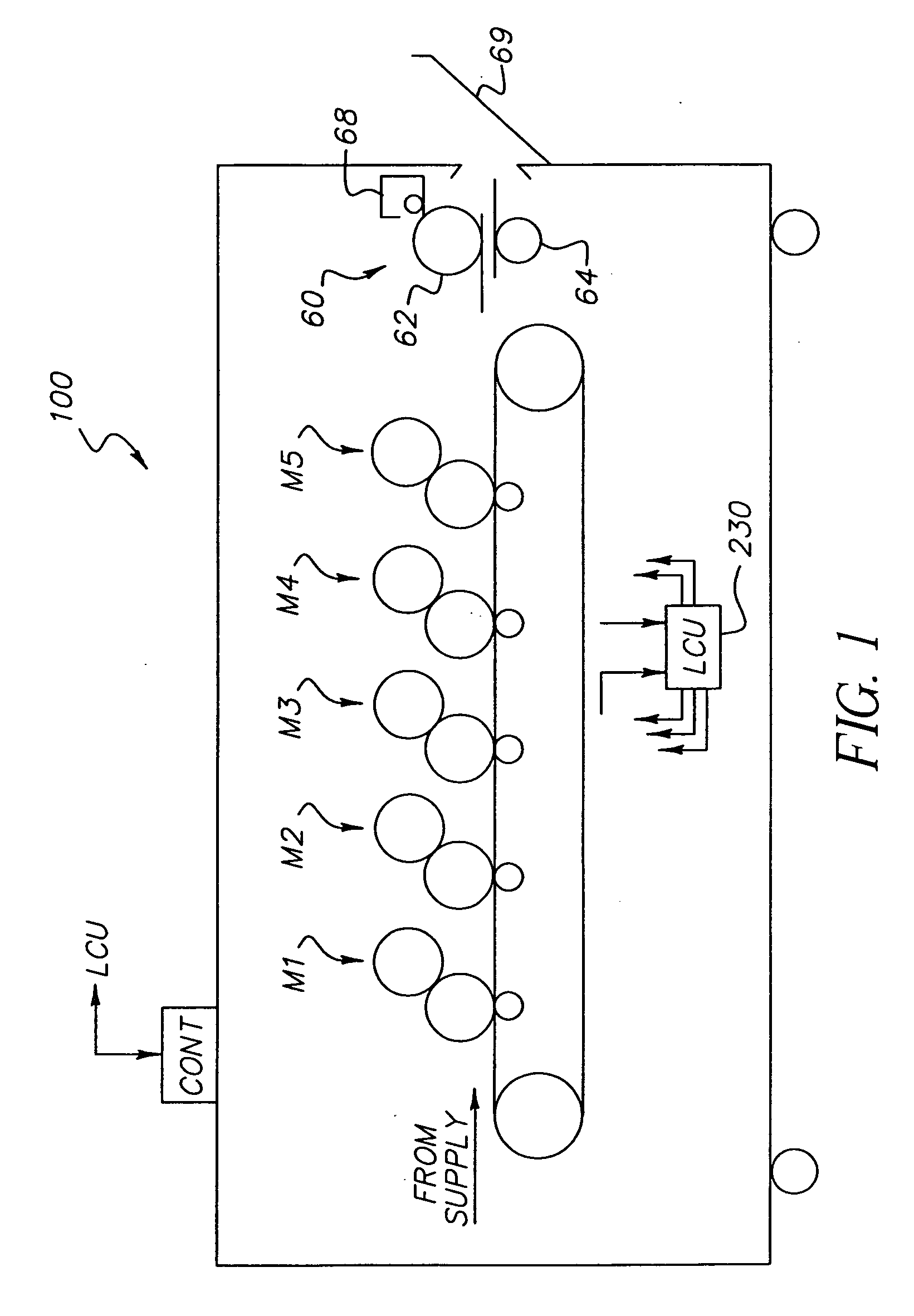
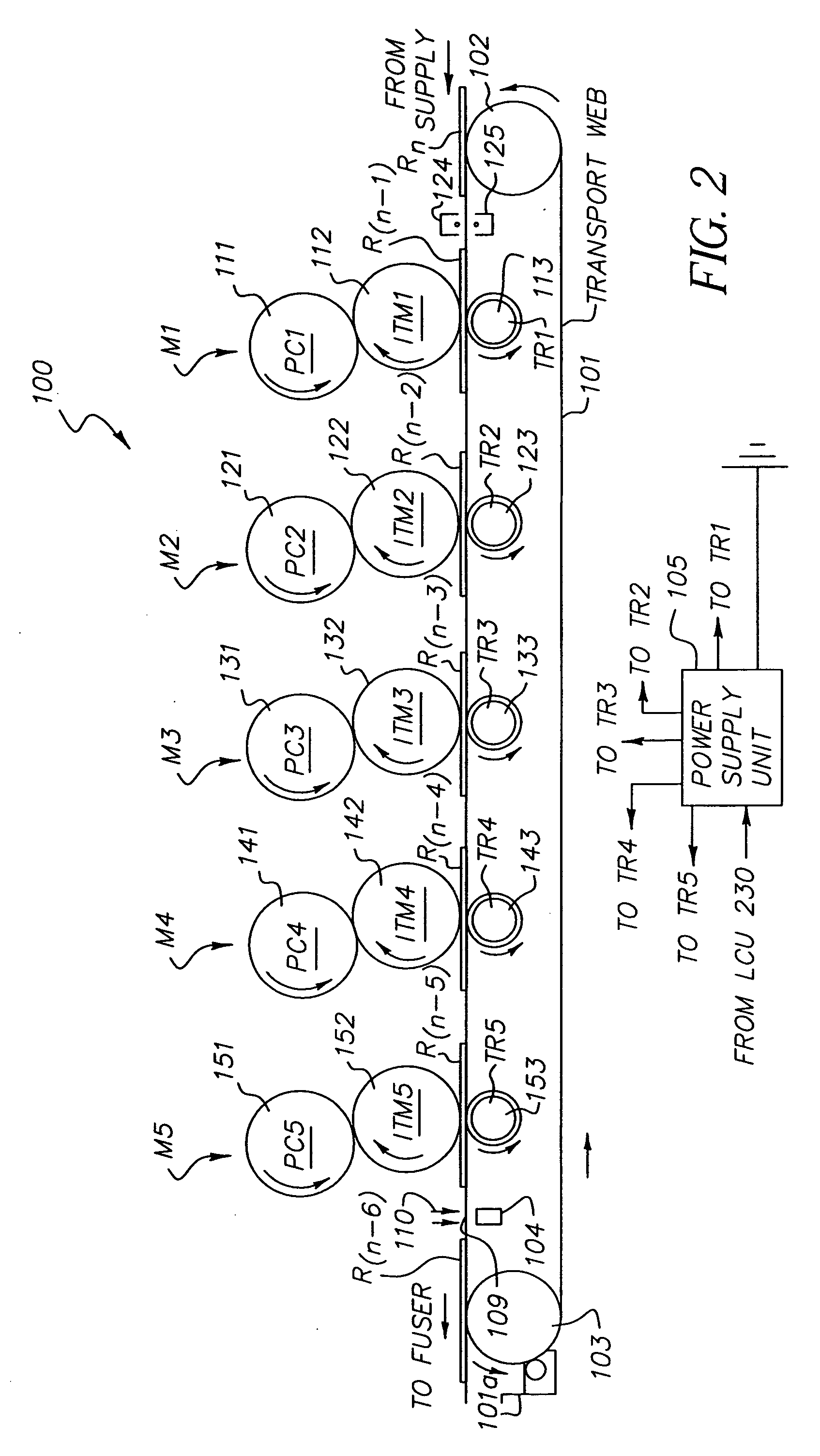
[0016]Referring now to the accompanying drawings, FIGS. 1-3 are side elevational views schematically showing portions of a typical electrographic print engine or printer apparatus suitable for printing of pentachrome images. Although one embodiment of the invention involves printing using an electrophotographic engine having five sets of single color image producing or printing stations or modules arranged in tandem, the invention contemplates that more or less than five colors may be combined on a single receiver member, or may include other typical electrographic writers or printer apparatus.

[0017]An electrographic printer apparatus 100 has a number of tandemly arranged electrostatographic image forming printing modules M1, M2, M3, M4, and M5. Each of the printing modules generates a single-color toner image for transfer to a receiver member successively moved through the modules. Each receiver member, during a single pass through the five modules, can have transferred in registra...


PUM


Abstract

Electrographic printing wherein raised information, with a distinct tactile feel, can be printed by electrographic techniques. Such electrographic printing comprises the steps of forming a desired print image, electrographically, on a receiver member utilizing standard size marking particles; and in an area of the formed print image, where desired tactile feel, raised information is to be formed, selectively forming such tactile feel, raised information utilizing marking particles of a substantially larger size than the standard size marking particles of the desired print image.

Description

FIELD OF THE INVENTION[0001]This invention relates in general to electrographic printing, and more particularly to selectively printing of tactile feel, raised information by electrography.BACKGROUND OF THE INVENTION[0002]One common method for printing images on a receiver member is referred to as electrography. In this method, an electrostatic image is formed on a dielectric member by uniformly charging the dielectric member and then discharging selected areas of the uniform charge to yield an image-wise electrostatic charge pattern. Such discharge is typically accomplished by exposing the uniformly charged dielectric member to actinic radiation provided by selectively activating particular light sources in an LED array or a laser device directed at the dielectric member. After the image-wise charge pattern is formed, the pigmented (or in some instances, non-pigmented) marking particles are given a charge, substantially opposite the charge pattern on the dielectric member and broug...

Claims


Application Information

Patent Timeline
IPC IPC(8): G03G15/06
CPCG03G15/221G09B21/02G03G15/321
Inventor TOMBS, THOMAS NATHANIELCHOWDRY, ARUNTAI, HWAI-TZUUTYAGI, DINESHASLAM, MUHAMMEDGOMES, EARL GREGORY
Owner EASTMAN KODAK CO
Why Eureka
Try Eureka