Spinal stabilization system with flexible guides

a technology of flexible guides and stabilization systems, which is applied in the field of spine support devices, can solve the problems of difficult positioning of the spacer between the guide rods, relative large surgical sites, and large surgical sites

Active Publication Date: 2008-07-03
ZIMMER BIOMET SPINE INC
View PDF32 Cites 145 Cited by
  • Summary
  • Abstract
  • Description
  • Claims
  • Application Information

AI Technical Summary

Benefits of technology

[0008]In another embodiment, the flexible guide may be formed from polymeric material. The polymeric material may be integrally molded to the head of the vertebral anchor, or it may be molded separately and thereafter secured to the head of the vertebral anchor. In yet another embodiment, at least part of the guide proximate the head portion of the vertebral anchor is non-polymeric, while the rest of the guide comprises polymeric material.

Problems solved by technology

One drawback of traditional implantation of such dynamic stabilization systems is that relatively large surgical sites are required to permit threading the cord through the screws and spacer once the spacer has been positioned between the screws.
While some dynamic stabilization systems have been proposed for permitting the top loading of a spacer and cord between pedicle screws using guide rods to direct the cord and spacer between the screws, these systems also require a relatively large surgical sites and present difficulties when the curvature of the spine causes a convergence of the guide rods that makes it difficult to position the spacer between the guide rods.

Method used


Image

  • Spinal stabilization system with flexible guides
  • Spinal stabilization system with flexible guides
  • Spinal stabilization system with flexible guides

Examples


Embodiment Construction

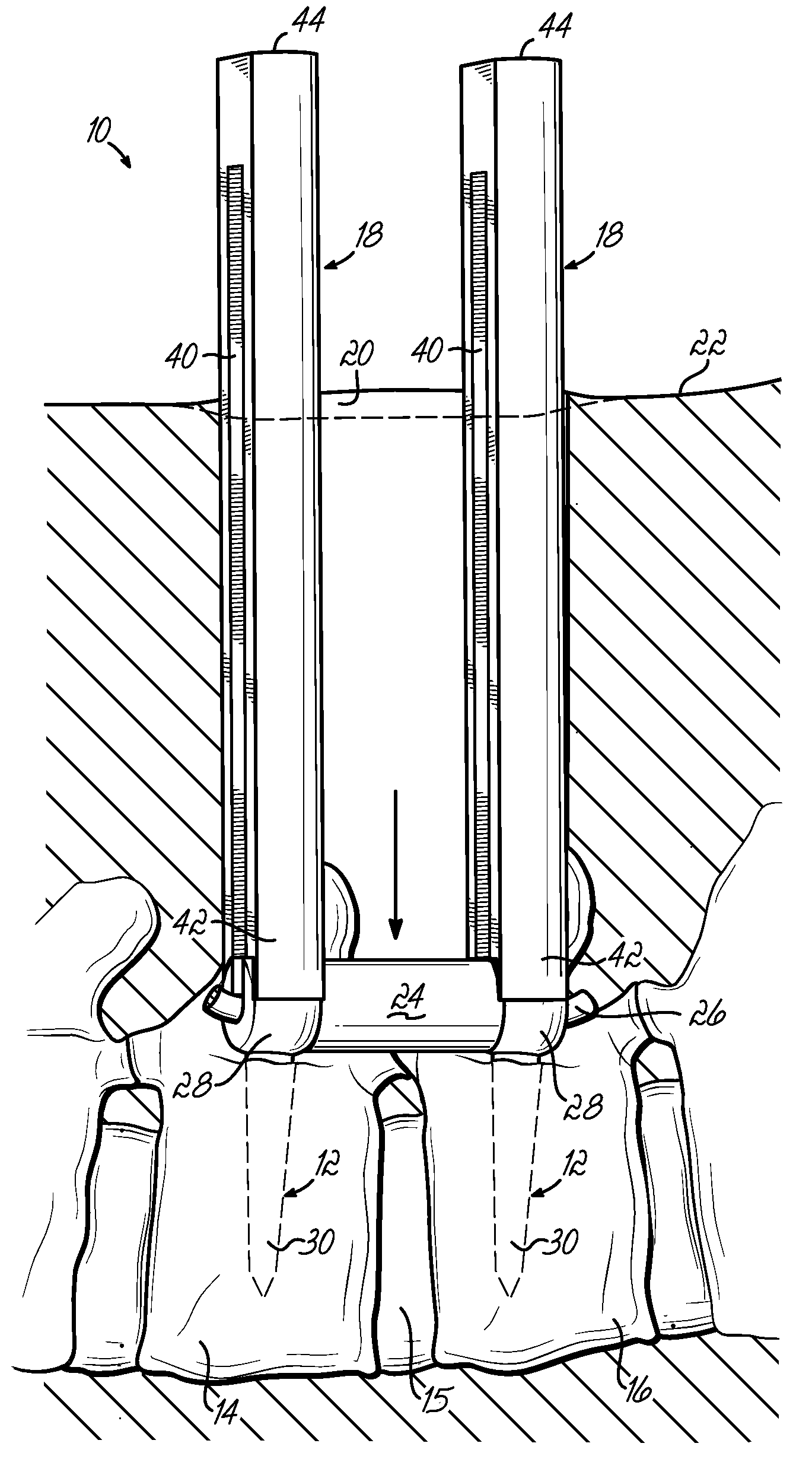
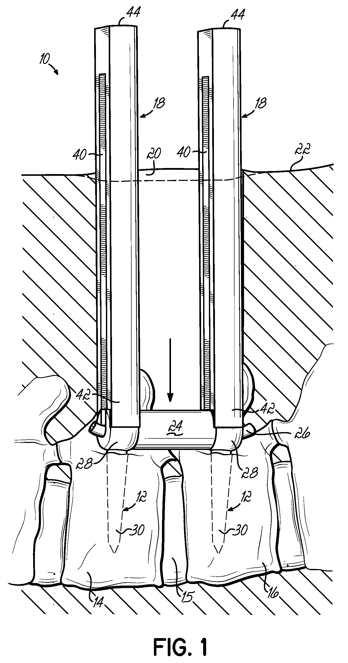
[0026]FIG. 1 depicts a portion of a human spine, with adjacent vertebrae 14, 16 separated by a disc 15. FIG. 1 also illustrates one embodiment of a spinal stabilization system 10 comprising anchors 12 installed into adjacent vertebrae 14, 16 of the spine using flexible, removable guides 18 inserted through a minimally invasive incision 20 formed through the patient's skin 22. In the embodiment shown, at least two anchors 12, shown here in the form of pedicle screws, are fixedly installed into the pedicle area of adjacent vertebrae 14, 16 and a flexible spacer 24 is disposed therebetween to control abnormal motion of the spine, while otherwise leaving the spinal segment mobile. The spacer 24 and pedicle screws 12 are coupled together by a flexible cord 26 threaded through the spacer 24 and secured to the heads 28 of the screws 12. Such spacers 24 and cords 26 may be similar to those used in the Dynesys® Dynamic Stabilization System available from Zimmer, Inc. of Warsaw, Ind. In one e...


PUM


Abstract

In one embodiment, a spinal stabilization apparatus includes a vertebral anchor having a head portion and a bone attachment portion. An elongate, flexible guide is removably coupled to the head portion of the vertebral anchor and has a channel extending longitudinally thereof and communicating with a slot in the head portion of the anchor. An elongate cord may be received within the channel to facilitate inserting and securing a spacer between pairs of anchors installed into adjacent vertebrae of a person's spine.

Description

TECHNICAL FIELD[0001]The present invention relates generally to spinal support devices, and more particularly to devices that facilitate installing an implantable system for providing dynamic stability of a person's spine.BACKGROUND OF THE INVENTION[0002]The treatment of acute and chronic spinal instabilities or deformities of the thoracic, lumbar, and sacral spine has traditionally involved the implantation of rigid rods to secure the vertebrae of a patient. More recently, flexible materials have been utilized in connection with securing elements, such as pedicle screws, to provide a dynamic stabilization of the spine. Such dynamic stabilization systems typically include a flexible spacer positioned between pedicle screws installed in adjacent vertebrae of person's spine. Once the spacer is positioned between the pedicle screws, a flexible cord is threaded through eyelets formed in the pedicle screws and an aperture through the spacer. The flexible cord retains the spacer between t...

Claims


Application Information

Patent Timeline
Patent Type & Authority Applications(United States)
IPC IPC(8): A61B17/70
CPCA61B17/025A61B17/7031A61B2017/0256A61B17/7085A61B17/7032
Inventor HESTAD, HUGHRICE, MARK
Owner ZIMMER BIOMET SPINE INC
Why Eureka
Try Eureka