Method For Measuring Doctor Blade Geometric Deviations

a geometric deviation and doctor blade technology, applied in the field of doctor blades, can solve problems such as inconsistent and unacceptable print quality

Active Publication Date: 2008-07-03
LEXMARK INT INC
View PDF9 Cites 9 Cited by
  • Summary
  • Abstract
  • Description
  • Claims
  • Application Information

AI Technical Summary

Problems solved by technology

Failure of the doctor blade to make uniform and consistent contact across the entire length of the developer roller will result in uneven toner amounts being transferred to the photoconductive drum, thereby resulting in inconsistent and unacceptable print quality.

Method used


Image

  • Method For Measuring Doctor Blade Geometric Deviations
  • Method For Measuring Doctor Blade Geometric Deviations
  • Method For Measuring Doctor Blade Geometric Deviations

Examples


Embodiment Construction

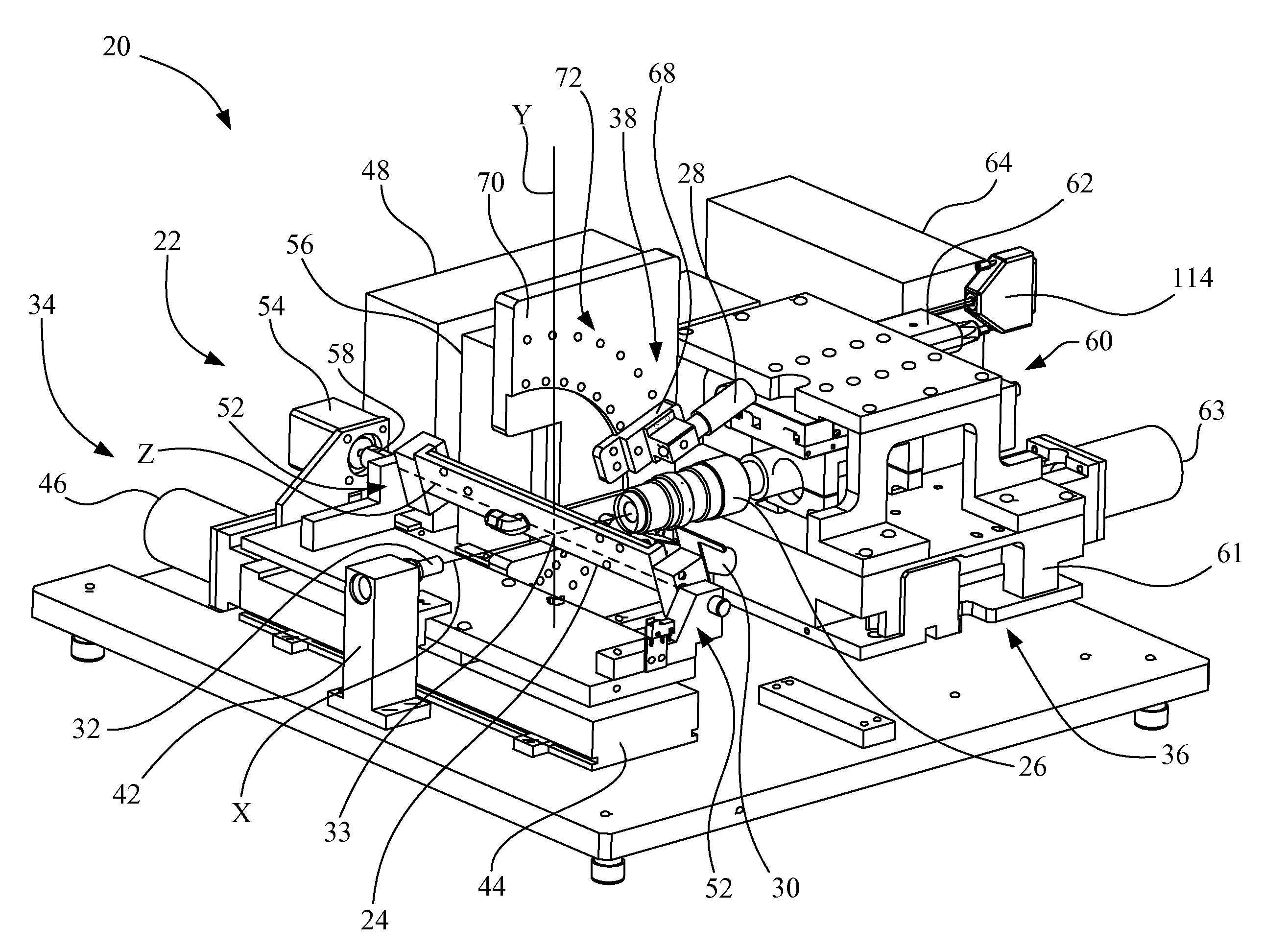
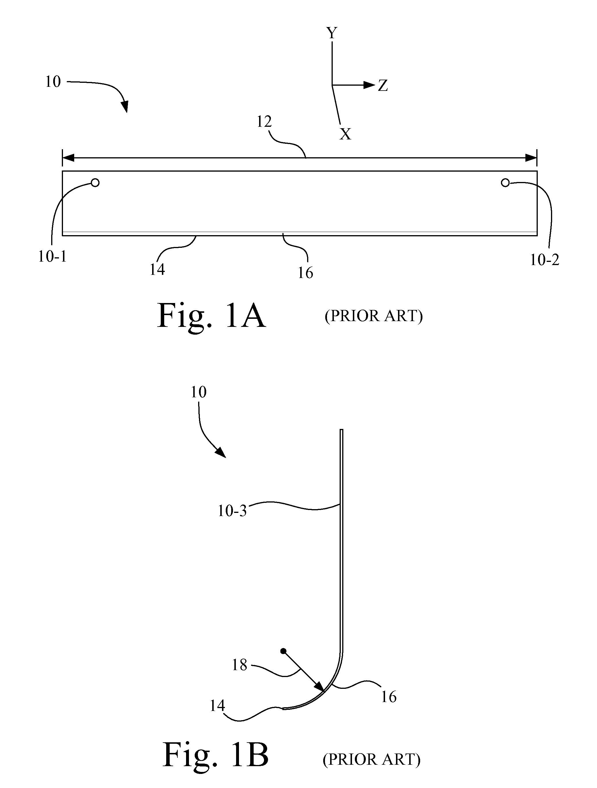
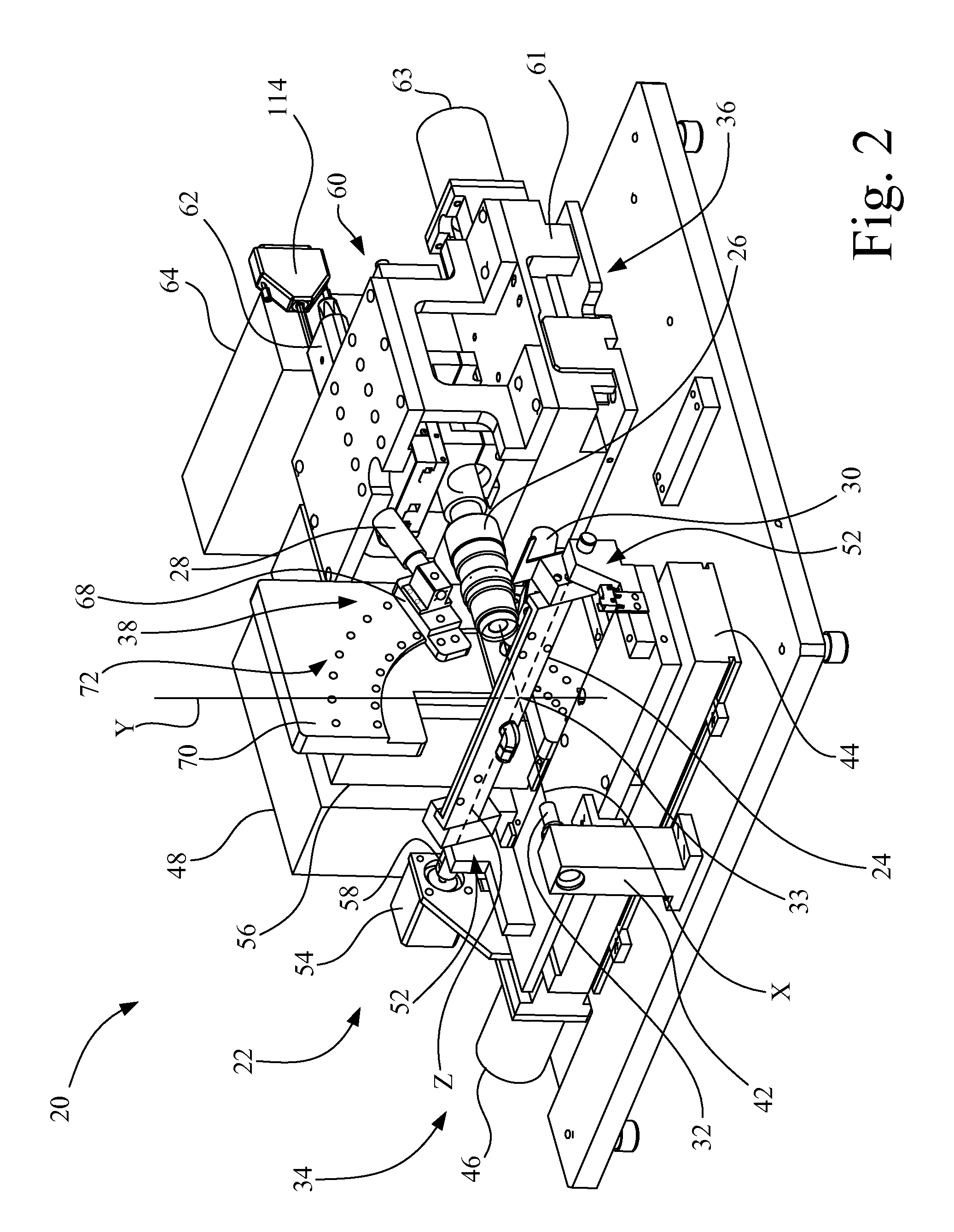
[0038]Referring now to the drawings and particularly to FIGS. 2-5, there is shown an apparatus 20 for measuring geometric deviations in a doctor blade, such as doctor blade 10 shown in FIGS. 1A and 1B. Apparatus 20 includes a mounting fixture 22, a doctor blade holding device 24, a camera 26, a first light source 28, a second light source 30, and a third light source 32.

[0039]Camera 26 may be, for example, a charge-coupled device (CCD) having a field of view of approximately one millimeter. Camera 26 defines an optical axis, which in turn defines an X-axis in a Cartesian coordinate system that will be used in describing the orientation of components of apparatus 20. A Y-axis is oriented vertically orthogonal to the X-axis. A Z-axis is oriented orthogonal to both the X-axis and the Y-axis. An origin 33 of the Cartesian coordinate system defines an intersection point, which may also be referenced by element number 33.

[0040]Mounting fixture 22 includes a mount 34 for mounting doctor bl...


PUM


Abstract

A method for measuring geometric deviations of a doctor blade using an apparatus, including initializing the apparatus, mounting the doctor blade to a doctor blade holding device, illuminating the doctor blade with light, positioning a first portion of the doctor blade at an optical axis of a camera, obtaining a first image signal from the camera that corresponds to the first portion of the doctor blade, generating a first doctor blade geometry value associated with the first image signal, and determining if a first geometric deviation of the doctor blade is within acceptable tolerance using the first doctor blade geometry value.

Description

CROSS-REFERENCE TO RELATED APPLICATIONS[0001]This is a continuation-in-part of U.S. patent application Ser. No. 11 / 616,956, entitled “APPARATUS FOR MEASURING DOCTOR BLADE GEOMETRIC DEVIATIONS”, filed Dec. 28, 2006.BACKGROUND OF THE INVENTION[0002]1. Field of the Invention[0003]The present invention relates to a doctor blade, and, more particularly, to a method for measuring doctor blade geometric deviations.[0004]2. Description of the Related Art[0005]Electrophotographic image forming devices, such as laser printers, include a drum having a rigid cylindrical surface that is coated along a defined length of its outer surface with a photoconductive material. The surface of the photoconductive drum is charged to a uniform electrical potential and then selectively exposed to light in a pattern corresponding to an original image. Those areas of the surface of the photoconductive drum exposed to light are discharged thus forming a latent electrostatic image on the photoconductive surface....

Claims


Application Information

Patent Timeline
Patent Type & Authority Applications(United States)
IPC IPC(8): G01B11/14
CPCG01B11/306G01B11/255
Inventor HOLECEK, THOMAS ALLENPATERSON, ROBERT L.
Owner LEXMARK INT INC
Why Eureka
Try Eureka