Structure of Hybrid Vehicle

a hybrid vehicle and structure technology, applied in the direction of propulsion parts, machines/engines, gas pressure propulsion mounting, etc., can solve the problems of affecting affecting the performance of the internal combustion engine, and bending of the pipe along its route, so as to suppress the reduction in the efficiency of cooling the secondary battery, reduce the effect of bending of the pipe, and reduce the effect of internal combustion engine performan

Inactive Publication Date: 2008-07-10
TOYOTA JIDOSHA KK
View PDF5 Cites 66 Cited by
  • Summary
  • Abstract
  • Description
  • Claims
  • Application Information

AI Technical Summary

Benefits of technology

[0007]An object of the present invention is to solve the aforementioned problems, and to provide a structure of a hybrid vehicle that suppresses reduction in the efficiency of cooling a secondary battery without placing a great limit on routing of an exhaust pipe.
[0009]With the structure of a hybrid vehicle thus configured, it is not necessary to detour around the battery pack when routing the exhaust passage from the internal combustion engine to the exhaust port. Accordingly, excessively bent route of the exhaust passage can be avoided, and the performance of the internal combustion engine can be prevented from being impaired. Here, the exhaust passage is provided so that it passes a position displaced from a position immediately below the intake chamber. Therefore, the effect of heat of the exhaust passage on the cooling air in the intake chamber is suppressed to be small, and thus an increase in the temperature of the cooling air before being provided to the plurality of battery cells can be suppressed. Thus, a significant reduction in the efficiency of cooling the secondary battery can be prevented.
[0012]With the structure of a hybrid vehicle thus configured, it is not necessary to detour around the battery pack when routing the exhaust passage from the internal combustion engine to the exhaust port. Accordingly, excessively bent route of the exhaust passage can be avoided, and the performance of the internal combustion engine can be prevented from being impaired. Here, the catalyst portion arranged at the exhaust passage is arranged at a position displaced from a position immediately below the intake chamber. Accordingly, the effect of heat generated at the catalyst portion due to catalytic reaction on the cooling air in the intake chamber can be suppressed to be small, and thus an increase in the temperature of the cooling air before being supplied between each of the plurality of battery cells can be suppressed. Thus, a significant reduction in the efficiency of cooling the secondary battery can be prevented.
[0014]With the structure of a hybrid vehicle thus configured, it is not necessary to detour around the battery pack when routing the exhaust passage from the internal combustion engine to the exhaust port. Accordingly, excessively bent route of the exhaust passage can be avoided, and the performance of the internal combustion engine can be prevented from being impaired. Here, the catalyst portion provided at the exhaust passage is arranged at a position displaced from a position immediately below the battery pack. Accordingly, an increase in the temperature of the cooling air flowing in the battery pack due to the heat generated at the catalyst portion by catalytic reaction can be suppressed. Thus, a significant reduction in the efficiency of cooling the secondary battery can be prevented.
[0017]With the structure of a hybrid vehicle thus configured, it is not necessary to detour around the battery pack when routing the exhaust passage from the internal combustion engine to the exhaust port. Accordingly, excessively bent route of the exhaust passage can be avoided, and the performance of the internal combustion engine can be prevented from being impaired. Here, when the cooling air is introduced from one end of the intake chamber and exhausted from the other end of the exhaust chamber, the flow rate of the cooling air flowing between each of the battery cells is greater in a position nearer to the other end than to one end, and a temperature distribution of the battery cells exists, in which the temperature is low in the position nearer to the other end and high in the position nearer to one end. When the cooling air is introduced from one end of the intake chamber and exhausted from one end of the exhaust chamber, the flow rate of the cooling air flowing between each of the battery cells is greater in a position nearer to one end than to the other end, and a temperature distribution of the battery cells exists, in which the temperature is low in the position nearer to one end and high in the position nearer to the other end. In the present invention, the exhaust passage extends in a position near to the other end and to one end in respective cases, and therefore the temperature distribution of the battery cells can be made small by the heat of the exhaust passage.
[0018]As described above, according to the present invention, a structure of a hybrid vehicle that suppresses reduction in the efficiency of cooling a secondary battery without placing a great limit on routing of an exhaust pipe can be provided.

Problems solved by technology

However, in this case, since there is no chamber below the secondary battery as in the up-flow or down-flow type, the battery pack is greatly affected by heat from under the floor panel when the battery pack is arranged on the floor panel of the vehicle.
This may impair the efficiency of cooling the secondary battery.
However, the exhaust pipe must be detoured around the battery case, and therefore the pipe is greatly bent along its route.
When the exhaust pipe is excessively bent in such a manner, exhaust efficiency may be reduced and the engine performance may be impaired.

Method used


Image

  • Structure of Hybrid Vehicle
  • Structure of Hybrid Vehicle
  • Structure of Hybrid Vehicle

Examples


first embodiment

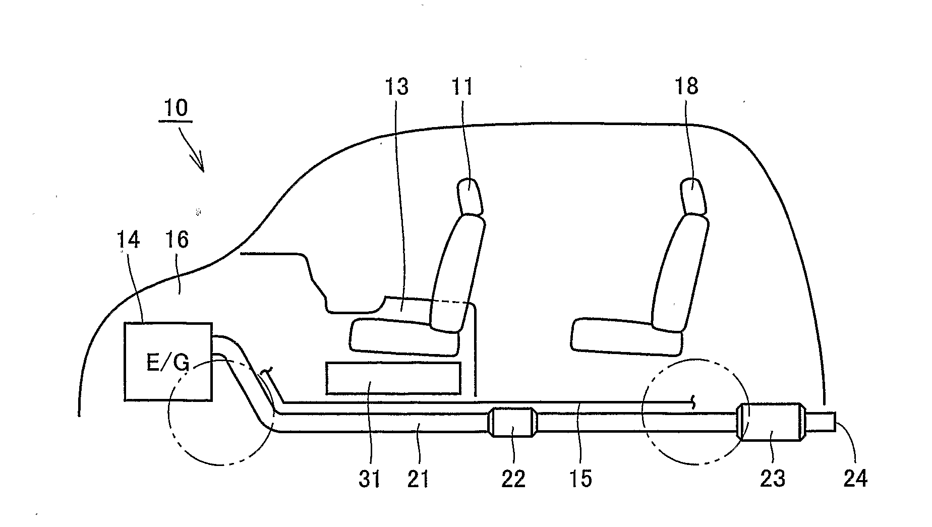
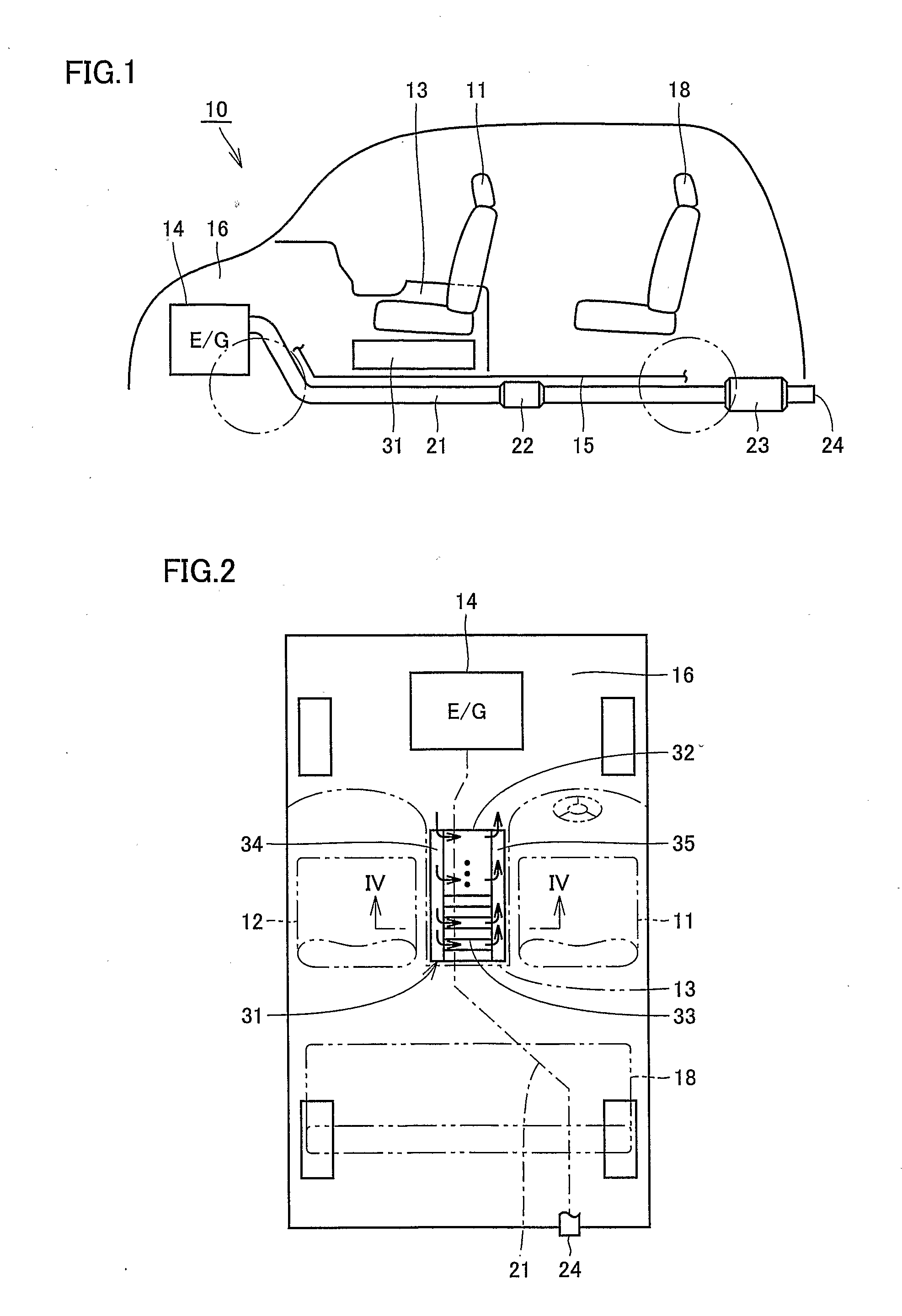
[0032]FIG. 1 is a side view of a hybrid vehicle in a first embodiment of the present invention. FIG. 2 is a plan view of the hybrid vehicle shown in FIG. 1. Referring to FIGS. 1 and 2, a hybrid vehicle 10 has as its source of motive power a gasoline engine 14 (hereinafter simply referred to as engine 14) and a motor electrically supplied from a secondary battery (battery) 32 that can be charged or discharged.

[0033]Engine 14 is stored in an engine room 16 formed on a front side of the vehicle. To an exhaust manifold of engine 14, an exhaust pipe 21 is connected. Exhaust pipe 21 extends from inside of engine room 16, passing below a floor panel 15, toward the rear of the vehicle. Floor panel 15 constitutes the floor board of the vehicle, and extends facing to the ground. Exhaust pipe 21 has, at its tip extending toward the rear of the vehicle, an exhaust port 24 opening toward the outside of the vehicle. The exhaust gas from engine 14 is guided through exhaust pipe 21 to the rear of t...

second embodiment

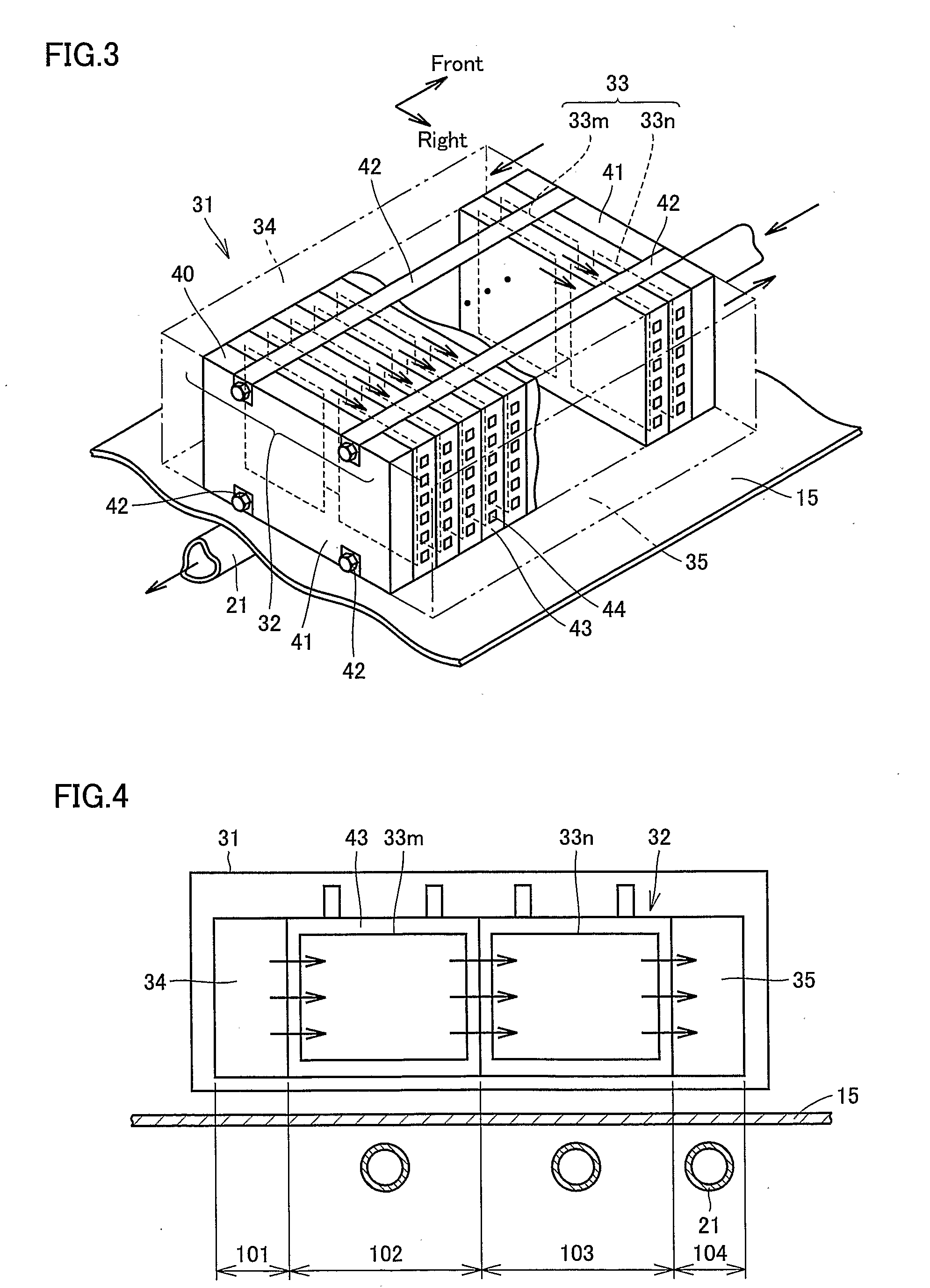
[0052]FIG. 7 is a plan view of a hybrid vehicle in a second embodiment of the present invention. FIG. 8 is a cross-sectional view of a battery pack along line VIII-VIII in FIG. 7. In the following, description of the structure being the same as in hybrid vehicle 10 in the first embodiment will not be repeated.

[0053]Referring to FIGS. 7 and 8, in the present embodiment, pairs of battery cells 33m and 33n aligned in parallel are stacked in the vehicle width direction to constitute secondary battery 32. Intake chamber 34 and exhaust chamber 35 are adjacent to secondary battery 32 in a horizontal direction perpendicular to the vehicle width direction along which battery cells 33 are stacked, that is, in the vehicle traveling direction. Exhaust pipe 21 extends immediately below battery pack 31, and extends through region 101 spreading immediately below intake chamber 34, regions 102 and 103 spreading immediately below battery cells 33m and 33n, respectively, and region 104 spreading imme...

third embodiment

[0059]FIG. 9 is a plan view of a hybrid vehicle in a third embodiment of the present invention. In the following, description of the structure being the same as in the hybrid vehicle in the first and second embodiments will not be repeated.

[0060]Referring to FIG. 9, in the present embodiment, battery cells 33 are stacked in the vehicle traveling direction to constitute secondary battery 32. Intake chamber 34 and exhaust chamber 35 are adjacent to secondary battery 32 in a horizontal direction perpendicular to the vehicle traveling direction along which battery cells 33 are stacked, that is, in the vehicle width direction. Exhaust pipe 21 extends immediately below battery pack 31, and three-way catalyst 22 is arranged at a position displaced from a position immediately below battery pack 31. That is, exhaust pipe 21 extends at a position overlapping with battery pack 31 when hybrid vehicle 10 is seen two-dimensionally, and three-way catalyst 22 is arranged at a position not overlappi...


PUM

PropertyMeasurementUnit
widthaaaaaaaaaa
structureaaaaaaaaaa
lengthaaaaaaaaaa

Abstract

A structure of a hybrid vehicle includes a battery pack arranged on a floor panel and an exhaust pipe extending from an engine, passing below the floor panel, to an exhaust port. The battery pack has a secondary battery constituted by a plurality of battery cells stacked in a vehicle traveling direction for supplying electric power to a motor, and an intake chamber provided adjacent to the secondary battery in a substantially horizontal direction perpendicular to the direction along which the plurality of battery cells are stacked for supplying cooling air between each of the plurality of battery cells. The exhaust pipe is provided so that it passes immediately below the battery pack and passes a position displaced from a position immediately below the intake chamber. With such a configuration, a structure of a hybrid vehicle that suppresses reduction in the efficiency of cooling a secondary battery without placing a great limit on routing of an exhaust pipe is provided.

Description

TECHNICAL FIELD[0001]The present invention generally relates to a structure of a hybrid vehicle having an internal combustion engine and a motor as its motive power source, and more particularly, to a structure of a hybrid vehicle including a battery pack of a side-flow type wherein cooling air flows in the horizontal direction.BACKGROUND ART[0002]As to a conventional structure of a hybrid vehicle, for example Japanese Patent Laying-Open No. 2001-138753 (Patent Document 1) discloses a vehicle lower body structure of a hybrid vehicle having an object of lowering the floor while reducing the length in the longitudinal direction of the vehicle. In the hybrid vehicle disclosed in Patent Document 1, a battery case storing a battery is arranged below a seat in the vehicle room. An exhaust pipe attached to an exhaust manifold of an engine extends below a floor panel toward an exhaust port situated at the rear of the vehicle. The exhaust pipe extends in a position not overlapping with the b...

Claims


Application Information

Patent Timeline
Patent Type & Authority Applications(United States)
IPC IPC(8): B60K6/22F01N3/02H02J7/00B60K1/04B60K6/24B60K6/28B60K11/04B60K11/06B60K13/04F01N1/00F01N13/08H01M50/209H01M50/249
CPCB60H1/00278H01M10/5073B60H2001/003B60K1/04B60K2001/005F01N3/10F01N3/106F01N13/08F01N2340/04H01M2/1077H01M10/5004H01M10/5016H01M10/5032H01M10/5059H01M10/5067B60H1/004H01M10/625H01M10/6563H01M10/647H01M10/6557H01M10/6566H01M10/613B60L2240/545B60L58/26B60L50/66B60L50/64Y02A50/20Y02T10/70Y02E60/10H01M50/249H01M50/209B60K6/22B60K6/28B60K11/00B60K13/00
Inventor WATANABE, KOHOSOKAWA, TOSHIYUKI
Owner TOYOTA JIDOSHA KK
Why Eureka
Try Eureka