
Structure of window covering support rack

a support rack and window covering technology, applied in the direction of suspension devices, stand/trestles, kitchen equipment, etc., can solve the problem of not being able to support the conventional window covering rack, and achieve the effect of facilitating the use of the window covering, retaining the rod, and passing smoothly

Inactive Publication Date: 2008-07-10
J PAXTON ENTERPRISES
View PDF12 Cites 39 Cited by
  • Summary
  • Abstract
  • Description
  • Claims
  • Application Information

AI Technical Summary

Benefits of technology

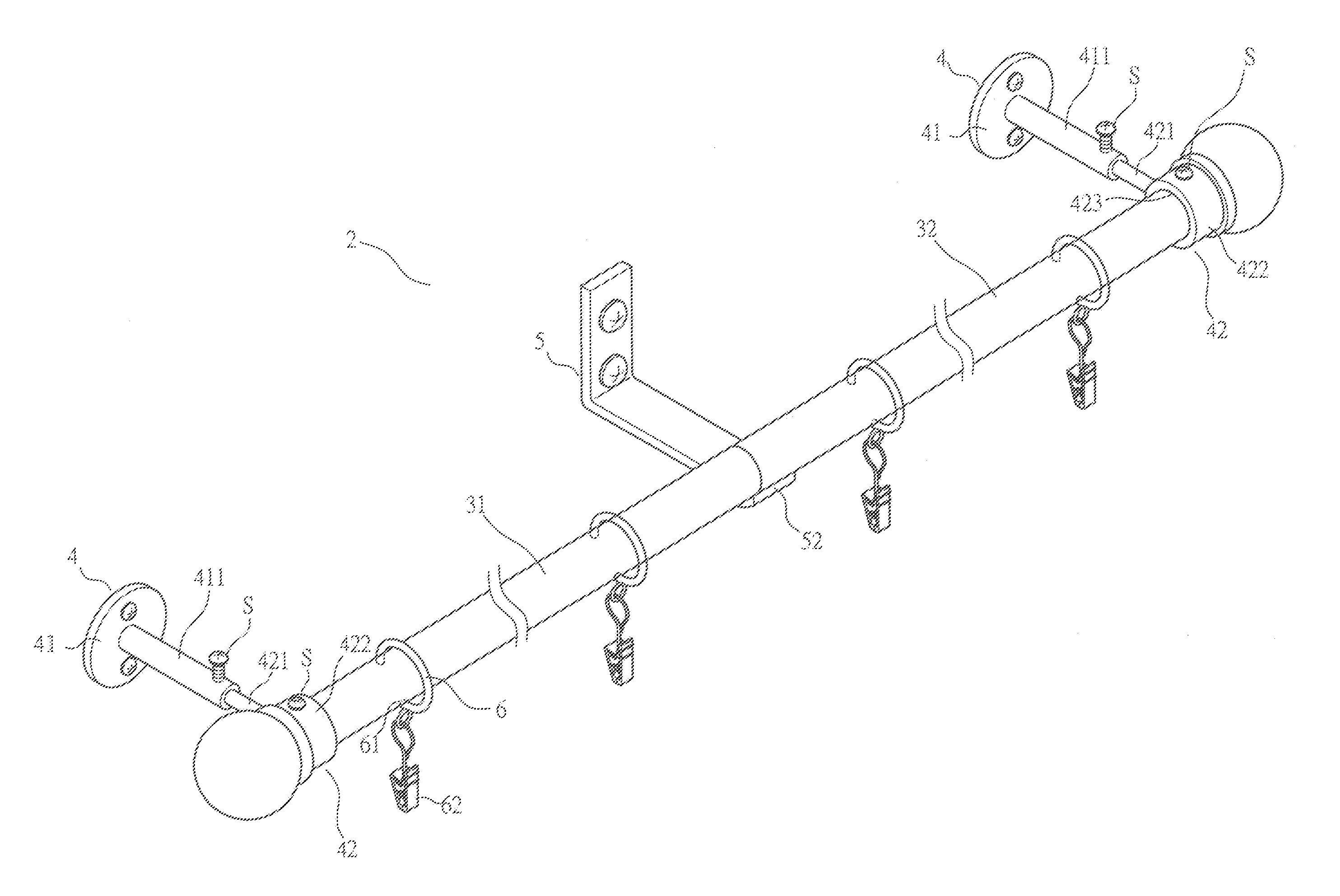
[0012]In an aspect of the present invention, there is provided a window covering support rack comprising a window covering support rod having opposite ends mounted to and supported by two end brackets that are mounted to a wall, and at least one intermediate bracket providing additional support to the rod. A plurality of hanger rings is fit over and movable along the rod. The intermediate bracket comprises an L-shaped plate having an end section mounted to the wall and a horizontally extending bottom support section extending from the end section and having a free end forming an arcuate recess for partially receiving and supporting the rod therein. A retention wall is formed on the bottom section of the intermediate bracket to stably retain the rod in the recess. Each hanger ring has a clip mounted thereto and depending therefrom for coupling a window covering, whereby the ring is securely retained on the rod by the weight of the window covering. The ring forms a side opening that is aligned to the bottom section of the intermediate bracket in a moving direction of the hanger ring along the rod so that the hanger ring is allowed to smoothly pass over the intermediate bracket to facilitate the use of the window covering.

Problems solved by technology

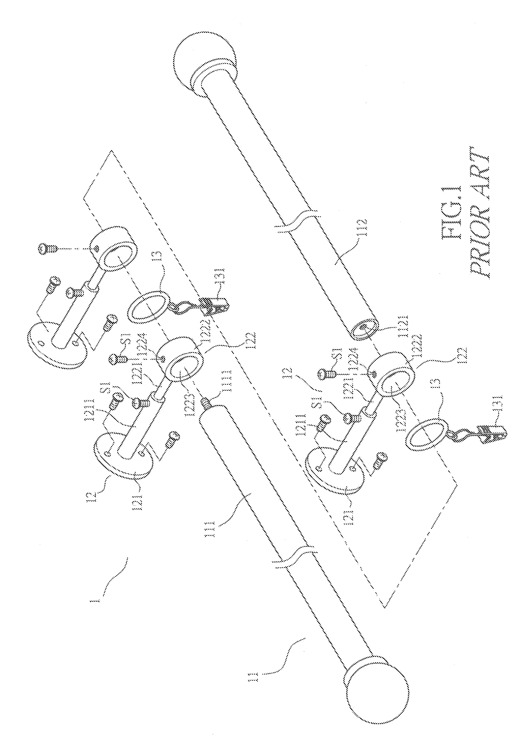
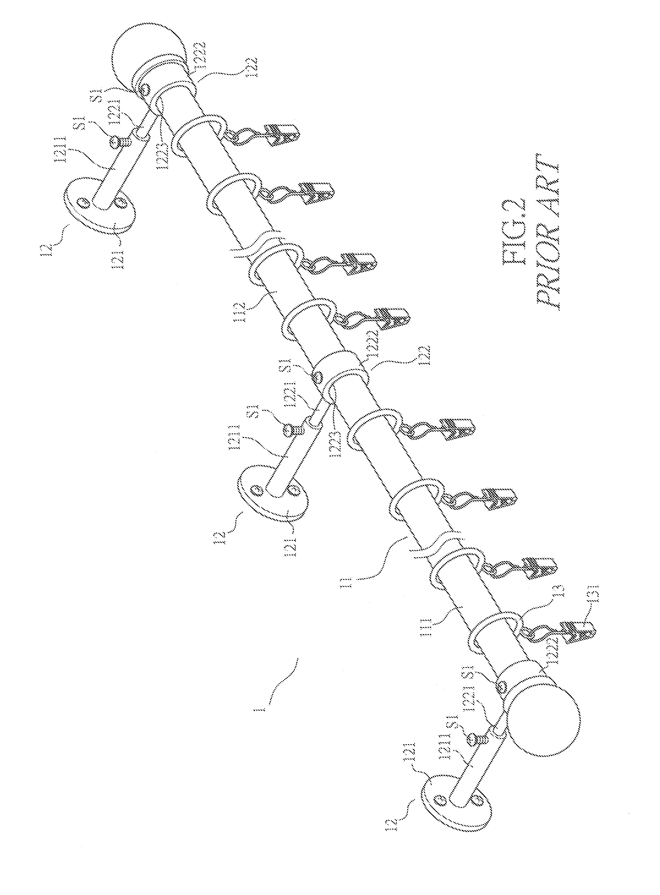
The conventional window covering support rack, although effective in soundly supporting a long rod 11 having a length exceeding five feet, suffers a major problem.
Thus, it is not possible for the conventional window covering support rack to allow the covering 2 to be completely moved to one side for fully exposing the window.

Method used


Image

  • Structure of window covering support rack
  • Structure of window covering support rack
  • Structure of window covering support rack

Examples


Embodiment Construction

[0028]The following descriptions are of exemplary embodiments only, and are not intended to limit the scope, applicability or configuration of the invention in any way. Rather, the following description provides a convenient illustration for implementing exemplary embodiments of the invention. Various changes to the described embodiments may be made in the function and arrangement of the elements described without departing from the scope of the invention as set forth in the appended claims.

[0029]With reference to the drawings and in particular to FIG. 4, a window covering support rack constructed in accordance with the present invention, generally designated with reference numeral 2, comprises a window covering support rod 3, end bracket 4, and at least one intermediate bracket 5, and a hanger rings 6.

[0030]The rod 3 can be a single elongate rod of a desired length or may be comprised of a plurality sections that are jointed together to form the rod 3. In the embodiments illustrate...


PUM


Abstract

A window covering support rack includes an elongate rod having opposite ends mounted to and supported by end brackets that are fixed to a wall and an intermediate bracket fixed to the wall between the end brackets and supporting the rod. The intermediate bracket includes an L-shaped plate having an end section fixed to the wall and a horizontal section extending from the rod section and having a free end forming a recess for partially receiving and supporting the rod therein. A retention wall is formed on the horizontal section of the intermediate bracket for stably retaining the rod in the recess. A plurality of hanger rings is fit over and movable along the rod. Each hanger ring has a side opening aligned with the horizontal section of the intermediate bracket to allow the hanger ring to pass over the intermediate bracket.

Description

BACKGROUND OF THE INVENTION [0001](a) Technical Field of the Invention[0002]The present invention relates to a window covering support rack, and in particular to a window covering support rack that allows passage of covering hanger ring or hanger hook through intermediate support brackets of the window covering support rack.[0003](b) Description of the Prior Art[0004]A conventional window covering set often comprise a piece of soft or flexible covering movably or non-movably supported on a support rack that is mounted to a wall above a window to be covered with the covering. The support rack comprises an elongate rod along which the covering is spread and hung and is selectively movable. The rod is supported, at opposite ends thereof, by brackets that are mounted to the wall. For rods of extended lengths, such as those being longer than 5 feet, one or more intermediate brackets are needed to ensure structural strength in supporting a long and thus heavy covering.[0005]FIG. 1 of the ...

Claims


Application Information

Patent Timeline
Patent Type & Authority Applications(United States)
IPC IPC(8): A47H1/142
CPCA47H1/02A47H2001/006A47H13/01A47H1/142
Inventor HUNG, CHIEN-HUA
Owner J PAXTON ENTERPRISES
Learn More