Method for manufacturing tool handle

a manufacturing tool and handle technology, applied in the direction of manufacturing tools, identification means, instruments, etc., can solve the problems of fading of printed the chance of being disengaged from the handle, and the inability to print or form raised indicia with delicacy or beautiful patterns or marks or words, etc., to achieve the effect of retaining

Inactive Publication Date: 2006-10-26
LIN HUNG WEI
View PDF6 Cites 14 Cited by
  • Summary
  • Abstract
  • Description
  • Claims
  • Application Information

AI Technical Summary

Benefits of technology

[0016] A peripheral groove may further be provided or formed on the handle member and may be disposed or located around the projection, to receive the peripheral flange of the covering, and / or to anchor or secure the covering to the handle member with such as force-fitted engagements. A concave chamber may further be provided or formed in the covering, to receive the panel and the projection of the handle member, and thus to further stably retain the panel to the handle member.

Problems solved by technology

However, the printed patterns or marks or words may be easily become faded after use.
However, the raised indicia are required to be formed or molded on the inner body, such that the raised indicia may not be printed or formed with delicacy or beautiful patterns or marks or words thereon.
However, the handle body have no anchoring or securing device to engage with the decorative blocks, such that the decorative blocks may have a good chance to be disengaged from the handle body after use.
In addition, similarly, the cavities are also required to be formed or molded on the cover sleeve with expensive mold device, such that the cavities may not be printed or formed with delicacy or beautiful patterns or marks or words thereon.
However, similarly, the cavities and the peripheral projections are also required to be formed or molded on the cover sleeve and on the handle body with expensive mold devices, such that the cavities and the peripheral projections also may not be printed or formed with delicacy or beautiful patterns or marks or words or indicia thereon.
However, similarly, the grooves are also required to be formed or molded in the outer protective coat with expensive mold devices, such that the grooves also may not be printed or formed with delicacy or beautiful patterns or marks or words thereon.

Method used


Image

  • Method for manufacturing tool handle
  • Method for manufacturing tool handle
  • Method for manufacturing tool handle

Examples


Embodiment Construction

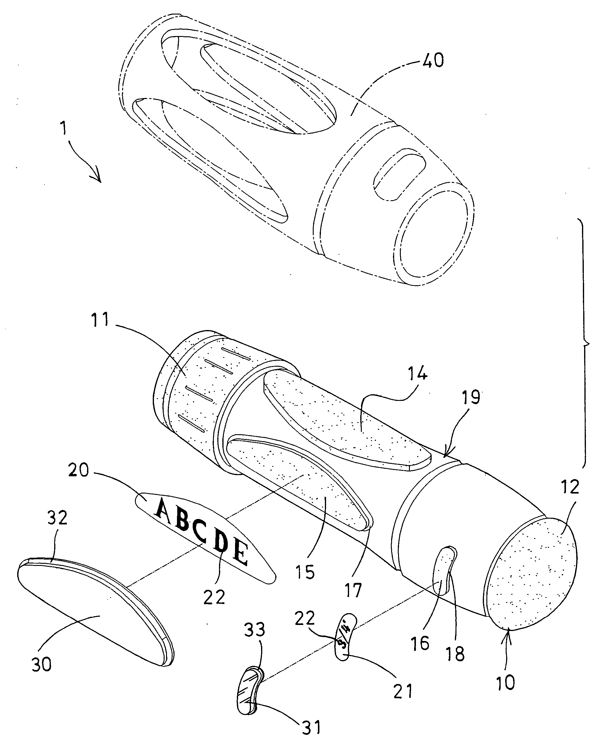
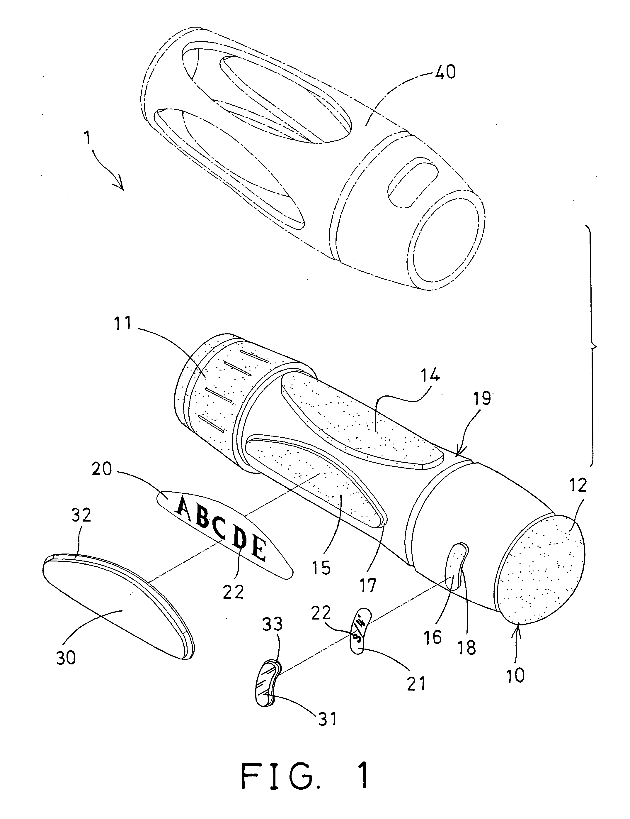
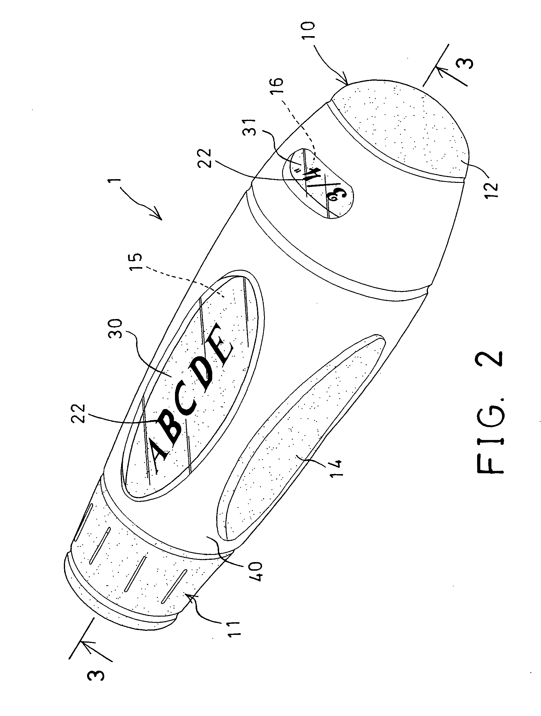
[0026] Referring to the drawings, and initially to FIGS. 1-3, a method in accordance with the present invention is provided for manufacturing a tool handle 1 which comprises a handle body 10 including a front peripheral protrusion 11 and a rear peripheral protrusion 12 formed thereon or extended therefrom two end portions, to form or define a peripheral recess 13 between the peripheral protrusions 11, 12 or in a middle portion 19 thereof, best shown in FIGS. 3, 7.

[0027] The tool handle 1 includes one or more projections 14, 15, 16 extended from the middle portion 19 of the handle body 10, and extended into the peripheral recess 13, and preferably includes one or more peripheral grooves 17, 18 formed around some of the projections 15, 16 respectively, to form a prototype as shown in FIG. 4. One or more decorative or identifying plates or panels 20, 21 may further be provided and attached onto the projections 15, 16 respectively (FIG. 5) and may be printed or formed or applied with d...


PUM

PropertyMeasurementUnit
transparentaaaaaaaaaa
semi-transparentaaaaaaaaaa
resilientaaaaaaaaaa

Abstract

A method for manufacturing a tool handle includes preparing a handle member having one or more projections, attaching a panel onto the projection of the handle member, attaching a covering onto the panel and the projection, the covering includes a peripheral flange. An outer sleeve is then molded onto the handle member, and is engaged with the peripheral flange of the covering, to retain the covering and the panel to the handle member. A peripheral groove may be formed on the handle member and around the projection, to receive the peripheral flange of the covering. A concave chamber may be formed in the covering, to receive the panel and the projection of the handle member.

Description

BACKGROUND OF THE INVENTION [0001] 1. Field of the Invention [0002] The present invention relates to a method for manufacturing tool handle, and more particularly to a method for manufacturing tool handle having a decorative or identifying panel attached thereto or provided therein. [0003] 2. Description of the Prior Art [0004] The most typical tool handles comprise a handle body having a molded outer sleeve or outer covering attached thereto and made of rubber or resilient plastic materials, for allowing the tool handles to be comfortably grasped or held by users. [0005] Normally, the outer sleeve or outer covering is subjected with a printing process, for applying marks, decorative patterns, identifying words, standard graduations, or the like, onto the outer peripheral portion of the outer sleeve or outer covering. However, the printed patterns or marks or words may be easily become faded after use. [0006] For allowing the marks, the decorative patterns, the identifying words, th...

Claims


Application Information

Patent Timeline
Patent Type & Authority Applications(United States)
IPC IPC(8): B21D39/03B21B1/46
CPCB21D53/70B25G1/00B25G1/105B29C45/14377B29C45/14467Y10T29/49982G09F3/00G09F23/00Y10T29/4998Y10T29/49826B29L2031/283
Inventor LIN, HUNG WEI
Owner LIN HUNG WEI
Why Eureka
Try Eureka