Cup holder with flexible protruding portion

a protruding portion and cup holder technology, applied in the field of cup holder, can solve the problems of more frequent deformation, increased resistance to insertion, and increased thickness of the protruding portion, so as to achieve stable retention of the cup, less resistance during insertion, and usability.

Active Publication Date: 2013-01-29
NIFCO INC
View PDF34 Cites 17 Cited by
  • Summary
  • Abstract
  • Description
  • Claims
  • Application Information

AI Technical Summary

Benefits of technology

[0024]The invention provides a cup holder that could stably retain a cup with various forms in an upstanding vertical condition. The cup holder has less resistance during insertion and taking-out of the cup, and the usability and the handling is better. Also, the cup holder is easy to mold.

Problems solved by technology

However, when a cup holder is integrally formed by using a flexible material as described in Patent Document 1, because of a molding problem, the thickness of the protruding portion requires to be formed relatively thick.
When integrally molding goods using flexible material, injection molding is used; but, defects such as filling defects and generation of air foam occurs more frequently if the wall thickness is thin using injection molding.
When the wall thickness of the protruding portion is thick, the increase in the stiffness of the protruding portion makes the deformation more difficult, which will increase the friction between the drink container and the protruding portion; thus, a problem such as the deterioration of the usability and the handling occurs.
Also, the cup holder described in Patent Document 1 has a protruding portion extending from the sidewall to the bottom portion making the drink container to reach the bottom portion more difficult.
Also, even if the drink container reaches the bottom portion, the bottom portion will lose its flatness due to the deformation of the protruding portion.
Thus, upstanding the drink container in a vertical position is difficult.

Method used


Image

  • Cup holder with flexible protruding portion
  • Cup holder with flexible protruding portion
  • Cup holder with flexible protruding portion

Examples


Embodiment Construction

[0033]A cup holder, which is the first embodiment of the present invention, will be explained with reference to the drawings.

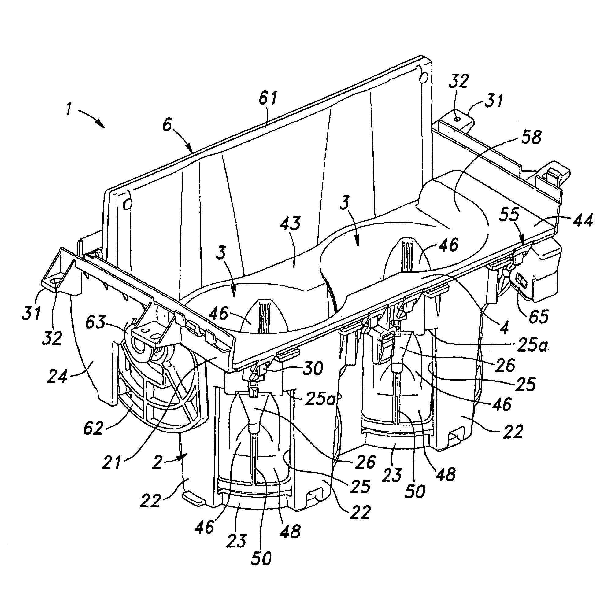
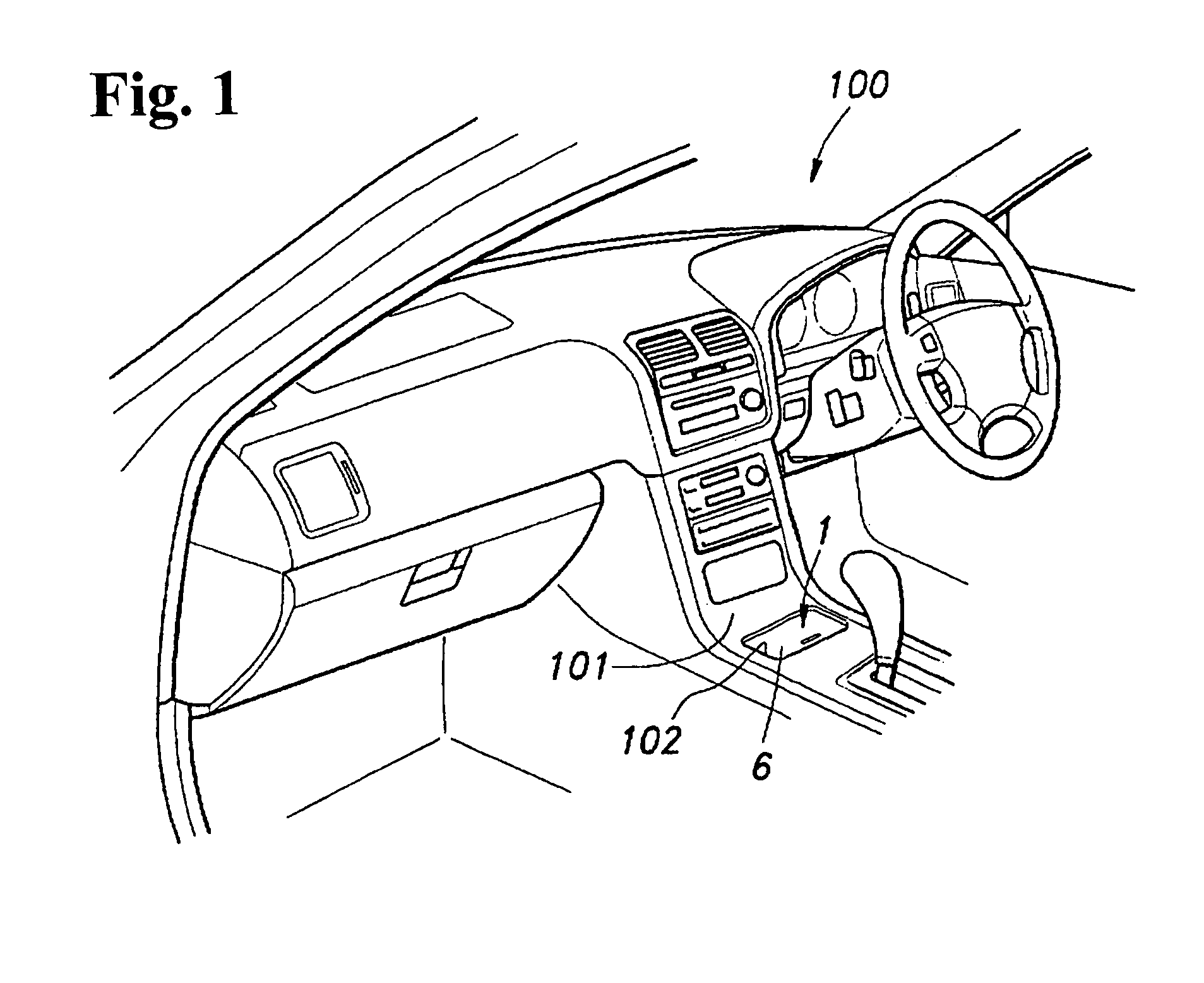
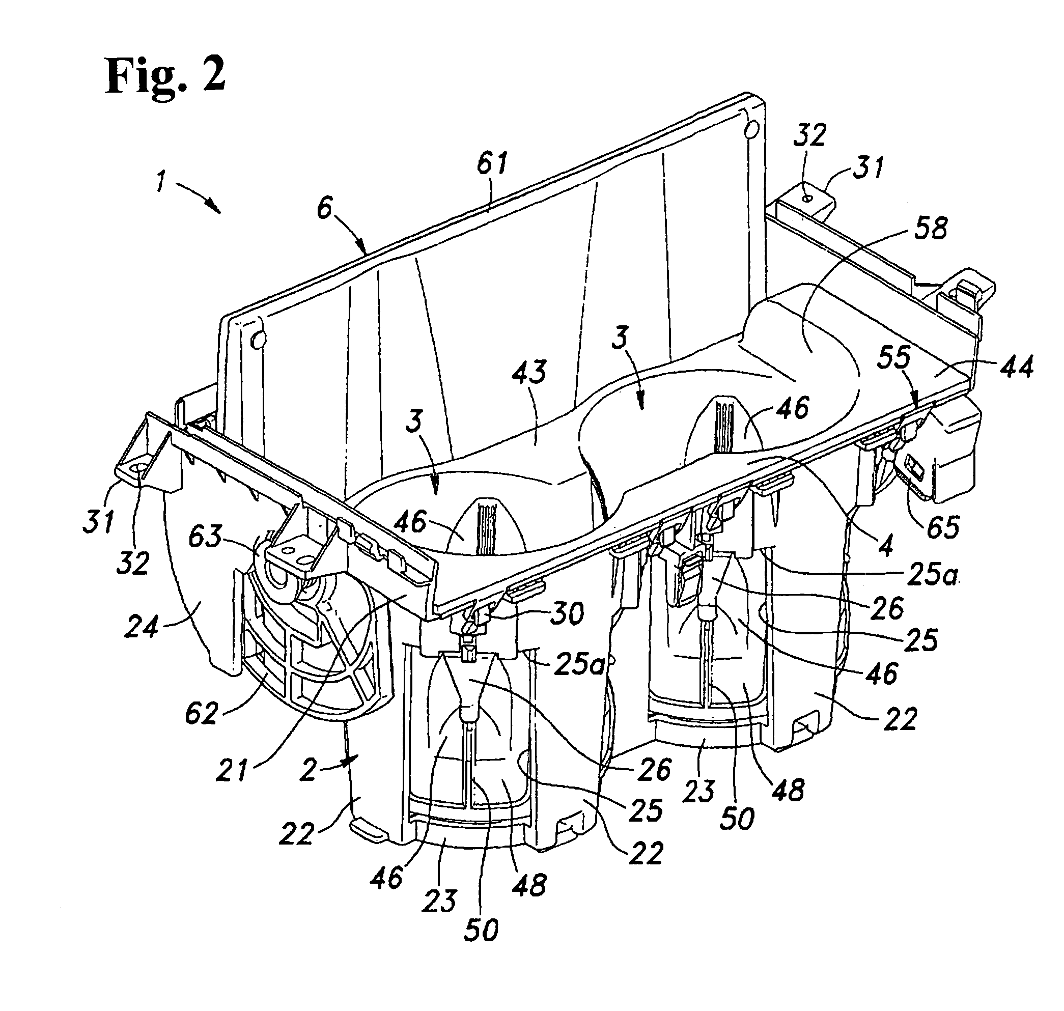
[0034]FIG. 1 is a perspective view of a cup holder attached to the vehicle according to this embodiment. FIG. 2 is a perspective view of the cup holder according to this embodiment. FIG. 3 is a perspective view of the cup holder according to this embodiment. FIG. 4 is a perspective view of a container of the cup holder according to this embodiment. FIG. 5 is a perspective view of the container of the cup holder according to this embodiment. FIG. 6 is a side view of the container viewed from the arrow VI of FIG. 4 according to this embodiment. FIG. 7 is a plan view of the container viewed from the arrow VII of FIG. 4 according to this embodiment. FIG. 8 is a cross-sectional view of the container viewed along the arrow VIII of FIG. 7 according to this embodiment. For convenience of explaining, the upper side of the paper is the upper side of the cup holder in FI...


PUM


Abstract

A cup holder for holding and retaining a cup includes a container integrally formed of a resin material as one structure with flexibility. The container includes a bottom portion, a cup retaining portion defined as a sidewall upstanding from the bottom portion, and at least one flexible protruding portion formed in the sidewall where the bottom portion does not contact. The flexible protruding portion is thinner in thickness than other portion of the side wall and protrudes towards an inside direction of the cup retaining portion. A rib is formed on an outside surface of the container to extend from the other portion of the side wall formed thicker than the protruding portion to a center of the protruding portion. An urging device is formed for pressing the protruding portion towards an inside of the container.

Description

TECHNICAL FIELD[0001]This invention relates to a cup holder, more specifically, an automotive cup holder that could stably retain a drink container of various sizes and shapes.BACKGROUND ART[0002]Conventionally, a console box of a car has a cup holder that could retain a drink container. There is a cup holder that has a cylindrical concave portion with a bottom, in which the concave portion is used to retain the drink container (cup). However, a drink container has various sizes and shapes, so a cup holder that could stably retain these drink containers in various sizes and shapes is needed.[0003]Through this viewpoint, there is a cup holder having a cylindrical concave portion with a bottom disposed integrally using flexible material and providing the sidewall of the concave portion with multiple protruding portions. (For example, Patent Document 1). The cup holder described in Patent Document 1 is fit for various shapes of drink containers because the drink container is retained b...

Claims


Application Information

Patent Timeline
Patent Type & Authority Patents(United States)
IPC IPC(8): A47K1/08
CPCB60N3/101B60N3/102B60N3/108B60N3/10B60R7/04
Inventor SOMA, TOSHIAKIFUKUDA, TSUYOSHI
Owner NIFCO INC
Why Eureka
Try Eureka