
Planetary gear device for reduction gearing

Active Publication Date: 2007-04-05
APEX DYNAMICS
View PDF6 Cites 15 Cited by
  • Summary
  • Abstract
  • Description
  • Claims
  • Application Information

AI Technical Summary

Benefits of technology

[0009] The primary objective of the present invention is to provide a planetary gear device including an oil supplying or filling structure for suitably feeding or supplying or filling lubricating oil to lubricate the gears and the pinions of the planetary gear device, and for decreasing frictions and vibrations and noises that may be generated between the gears and the pinions, and thus for increasing the working life of the gears and the pinions of the planetary gear device.
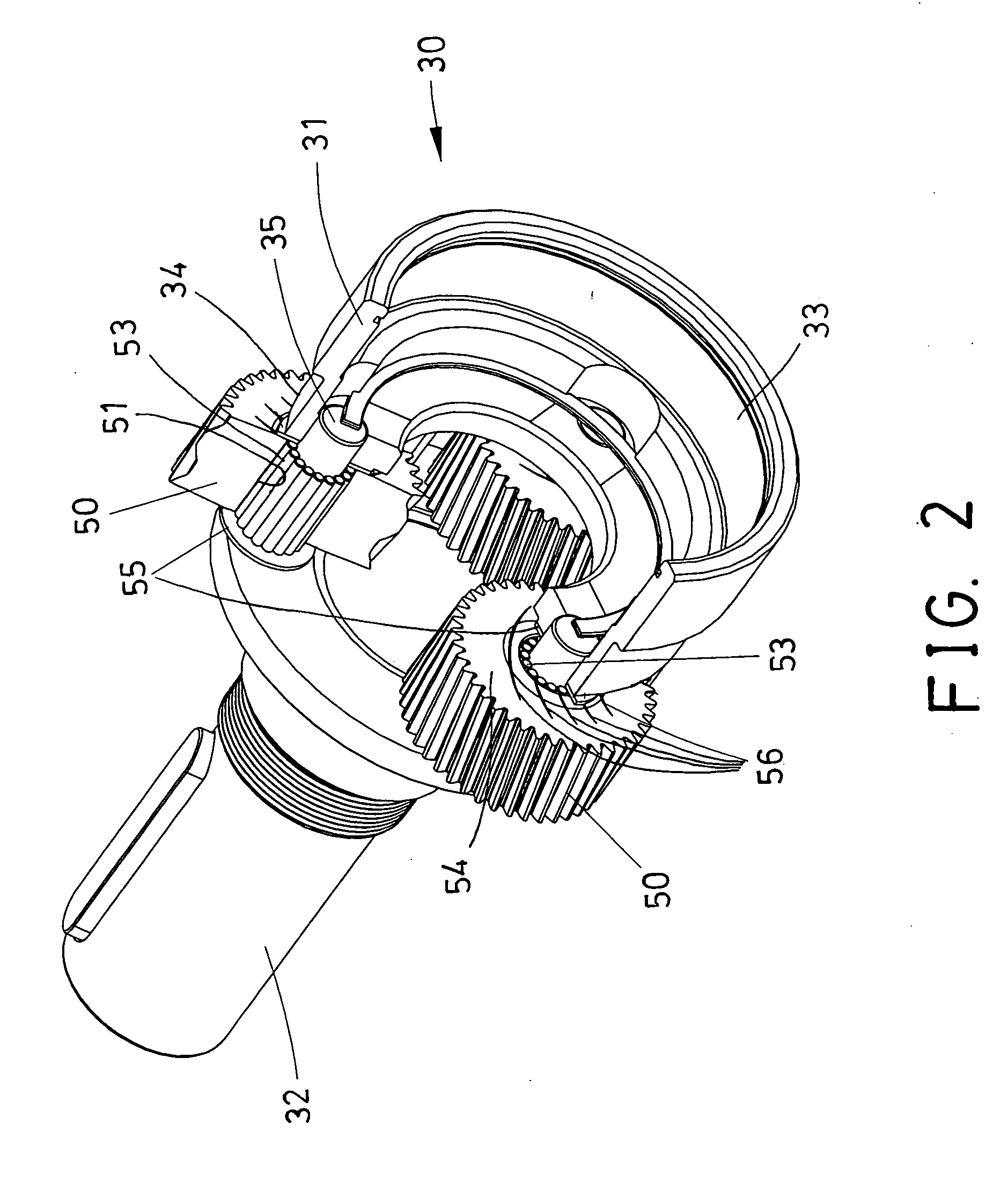
[0012] The planet pinions each includes two side portions each having a cap provided thereon, for enclosing the peripheral channel which is formed between the planet pinion and the axle, and for stably retaining the rollers within the bore of the planet pinion, and for preventing the rollers from being disengaged from the planet pinion and the axle.
[0013] For example, the caps may either be attached to the axles respectively, or attached to the side portions of the planet pinions respectively, for enclosing the peripheral channel which is formed between the planet pinion and the axle, and thus for stably retaining the rollers within the bore of the planet pinion, and for preventing the rollers from being disengaged from the planet pinion and the axle.

Problems solved by technology

However, the planet wheel members are directly and rotatably attached onto the planet carrier with shafts, and have no bearing devices engaged or provided between the planet wheel members and the shafts, such that an increased friction may be generated between the planet wheel members and the shafts, and such that an increased noise and vibration may be generated between the planet wheel members and the shafts after use.

Method used


Image

  • Planetary gear device for reduction gearing
  • Planetary gear device for reduction gearing
  • Planetary gear device for reduction gearing

Examples


Embodiment Construction

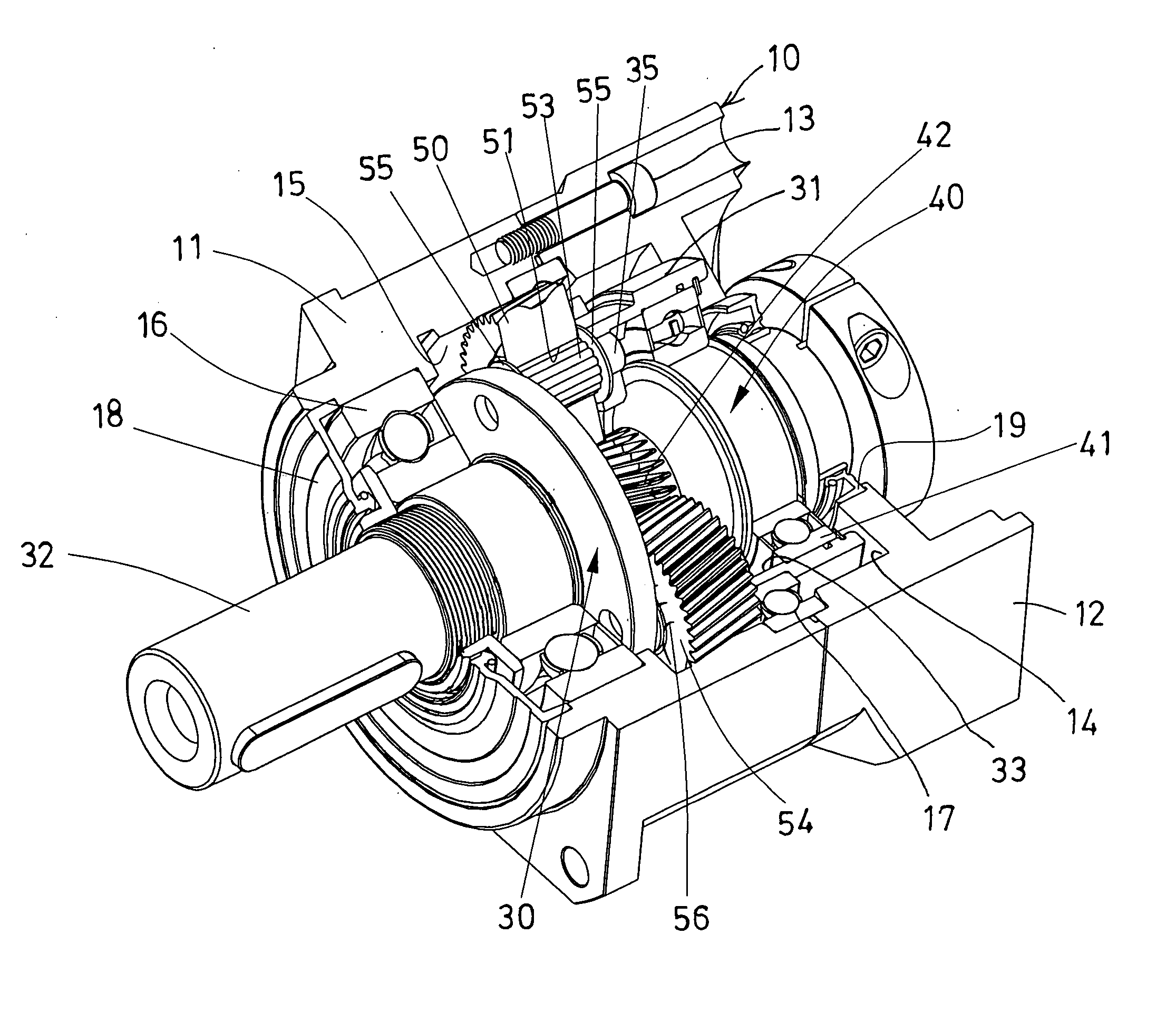
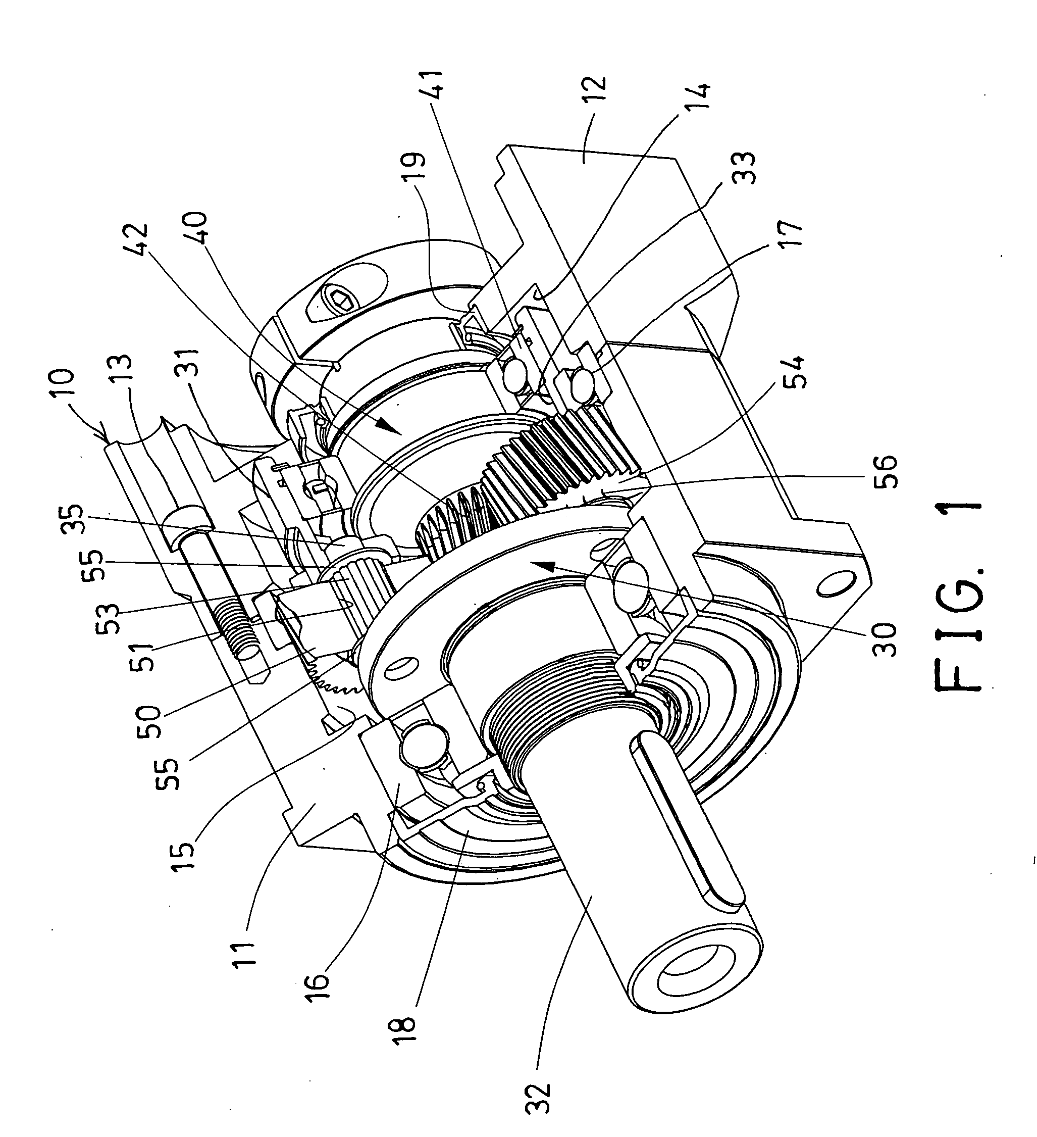
[0023] Referring to the drawings, and initially to FIGS. 1-4, a planetary gear device in accordance with the present invention comprises an outer housing 10 which may include two or more housing members 11, 12 coupled or secured together with such as fasteners 13, and which may include a chamber 14 formed therein, for rotatably receiving a follower 30 therein, and which includes an internal gear 15 formed or provided therein.

[0024] For example, the follower 30 includes a carrier 31 rotatably received or engaged within the chamber 14 of the housing 10 with one or more bearings 16, 17, and one or more oil seal members 18 attached to the housing 10 and engaged with the bearings 16, for confining or retaining lubricating member or grease or oil that may be provided or filled or fed into the bearings 16, to allow the bearings 16 to be suitably lubricated.

[0025] The follower 30 includes an output shaft 32 extended from the carrier 31, and preferably engaged with the bearing 16, and exte...


PUM


Abstract

A planetary gear device includes a housing having a chamber for receiving lubricating member and having an internal gear, a carrier rotatably received in the chamber of the housing and having an output shaft and having a number of openings for rotatably receiving planet pinions. The planet pinions are engaged with the internal gear of the housing, and each includes a bore for receiving an axle, and a number of rollers received between the planet pinion and the axle to act as a bearing device for smoothly attaching the planet pinions on the axles. The planet pinions each has one or two side portions each having one or more slots for filling the lubricating member into the bore of the planet pinion.

Description

BACKGROUND OF THE INVENTION [0001] 1. Field of the Invention [0002] The present invention relates to a planetary gear device for a reduction gearing, and more particularly to a planetary gear device having an oil supplying or filling structure for suitably feeding or supplying or filling lubricating oil to lubricate the gears and the pinions of the planetary gear device, and for decreasing frictions and vibrations and noises that may be generated between the gears and the pinions, and thus for increasing the working life of the gears and the pinions of the planetary gear device. [0003] 2. Description of the Prior Art [0004] Typical planetary gear devices have been developed and provided for coupling to a spindle or an output shaft of a motor, and for acting as a reduction gearing, in order to generate or to provide a reduced output rotational speed. Normally, the typical planetary gear devices comprise a number of planet wheel members rotatably attached to a planet carrier, and enga...

Claims


Application Information

Patent Timeline
IPC IPC(8): F16H57/08F16H57/04
CPCF16H57/0463F16H57/0482F16H57/082
Inventor CHANG, ROBIN C.S.
Owner APEX DYNAMICS
Learn More