Positioning device of oral implanting robot vision navigation system

A technology of robot vision and navigation system, which is applied in the field of positioning device of dental implant robot vision navigation system, can solve the problems of inability to directly locate the predetermined implant site, time-consuming and labor-intensive operation, complex structure, etc., to save manpower and operation space, save The effect of removing cumbersome steps and simplifying the operation steps

Active Publication Date: 2016-03-02
BEIJING YAKEBOT TECH CO LTD
View PDF10 Cites 14 Cited by
  • Summary
  • Abstract
  • Description
  • Claims
  • Application Information

AI Technical Summary

Problems solved by technology

[0005] The visual navigation system of the robot is equivalent to the eyes of the robot, which can make it accurately locate the predetermined implant site. However, due to the narrow operating space of the oral cavity and the obstruction of the buccal soft tissue, the "eyes" of the robot cannot directly locate the predetermined implant site. In order to solve this problem, it is necessary to design a positioning device, which is loaded on the dentition to be implanted and repaired, and forms a rigid connection with the marker (Marker) placed outside the mouth. The robot vision system recognizes the marker (Marker) on it. To indirectly locate the intended planting site
[0006] At present, in the clinically used oral implant surgery navigation system (such as IGI), the device loaded on the dentition in the positioning device used is made by lamination method, which needs to prepare the dentition model, lamination molding, and The steps such as grinding and polishing can only be completed, and then the self-curing resin is used to bond the external marking bracket together. Infrared marking also needs a matching power supply, resulting in a complex structure

Method used


Image

  • Positioning device of oral implanting robot vision navigation system
  • Positioning device of oral implanting robot vision navigation system
  • Positioning device of oral implanting robot vision navigation system

Examples


Embodiment Construction

[0029] The present invention is further described below in conjunction with accompanying drawing.

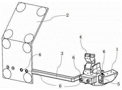
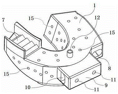
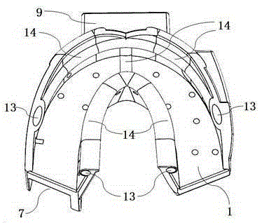
[0030] Such as figure 1 As shown, a positioning device for a visual navigation system of an oral implant robot includes a tray 1, a marking plate 2, a connecting rod 3, an opening retainer 4, an endoscope bracket 5, and a retaining screw 6. It is characterized in that the tray 1 and The marking plate 2 is connected through the connecting rod 3, wherein the tray handle 9 of the tray 1 is matched with the inserting tray part 20 of the connecting rod 2 through the connecting rod socket 10, and the retaining screw hole A11 of the tray handle 9 is inserted into the tray part 20. The retaining screw hole C22 provided on the top is fixed by the retaining screw 6, the retaining screw hole B17 of the marking plate 2 is coordinated with the retaining screw hole C22 of the connecting part A19 of the connecting rod 3 and fixed by the retaining screw 6, and the opening remains The holder 4 ...


PUM


Abstract

The invention discloses a positioning device of an oral implanting robot vision navigation system. The positioning device comprises a tray, a marking plate, a connecting rod, an opening retainer, an endoscope support and retaining screws. A tray handle of the tray is fixed through one retaining screw after being matched with a tray inserting portion of the connecting rod in position through a connecting rod inserting hole. A retaining screw hole B in the marking plate is fixed through one retaining screw after being matched with a retaining screw hole C of a connecting portion A of the connecting rod in position. The opening retainer is meshed with the interior of an opening retainer clamping groove in the tray through a toothed opening in the lower portion of the opening retainer. The endoscope support is fixed through one retaining screw after being matched with a retaining screw hole D in the endoscope support in position through an endoscope support inserting hole. According to the scheme, the operation steps are simplified, after the appropriate tray is selected according to clinic requirements, the tray can be stably fixed to a dentition by the adoption of a silicone rubber impression film preparation method, the tedious steps needed by manufacturing a device loaded on the dentition through a membrane pressing method are omitted, and preoperative preparation time and the patient treatment frequency are reduced.

Description

technical field [0001] The invention belongs to the technical field of surgical medical instruments, and in particular relates to a positioning device for a vision navigation system of an oral implant robot. Background technique [0002] Oral implants are currently the most effective way to replace missing teeth. The technical point of dental implantology is how to accurately prepare the cavity and implant the implant according to the predetermined angle and depth at the appropriate position of the patient's jaw. With the development of computer-aided implant system (CAI), especially the application of CT technology in the field of oral implants, the problems of image distortion and overlap inherent in conventional two-dimensional perspective imaging technology have been solved, and the anatomy of the surgical area can be accurately judged from three-dimensional images. Conditions, including bone quality, bone quantity, mandibular canal and maxillary sinus position, etc., a...

Claims


Application Information

Patent Timeline
Patent Type & Authority Applications(China)
IPC IPC(8): A61C19/04A61C8/00
CPCA61C8/00A61C19/04
Inventor 白石柱赵铱民吴秦谢瑞胡磊王利峰李征宇
Owner BEIJING YAKEBOT TECH CO LTD
Why Eureka
Try Eureka