Clamp for climate control device

a technology for climate control devices and clamps, which is applied to seat heating/ventilation devices, chairs, stools, etc., can solve the problems of seated occupants' back and other pressure points being sweaty, vehicle seats can become very hot and uncomfortable for the occupants, and problems that have been experienced with existing climate control systems for seats

Inactive Publication Date: 2008-07-10
AMERIGON INC
View PDF13 Cites 82 Cited by
  • Summary
  • Abstract
  • Description
  • Claims
  • Application Information

AI Technical Summary

Benefits of technology

[0013]Another aspect of the present invention is climate control apparatus for providing air to at least a portion of a vehicle seat comprising a first rail and a second rail, the first rail comprising a bend that extends radially away from a longitudinal axis of the rail. The apparatus includes a panel and a first conn

Problems solved by technology

For example, in an automotive vehicle exposed to summer weather, where the vehicle has been parked in an unshaded area for a long period of time, the vehicle seat can become very hot and uncomfortable for the occupant for some time after entering and using the vehicle, even with normal air conditioning.
Furthermore, even with normal air conditioning, on a hot day, the seated occupant's back and other pressure points may remain sweaty while seated.
There are, however, problems that have been experienced with exist

Method used


Image

  • Clamp for climate control device
  • Clamp for climate control device
  • Clamp for climate control device

Examples


Embodiment Construction

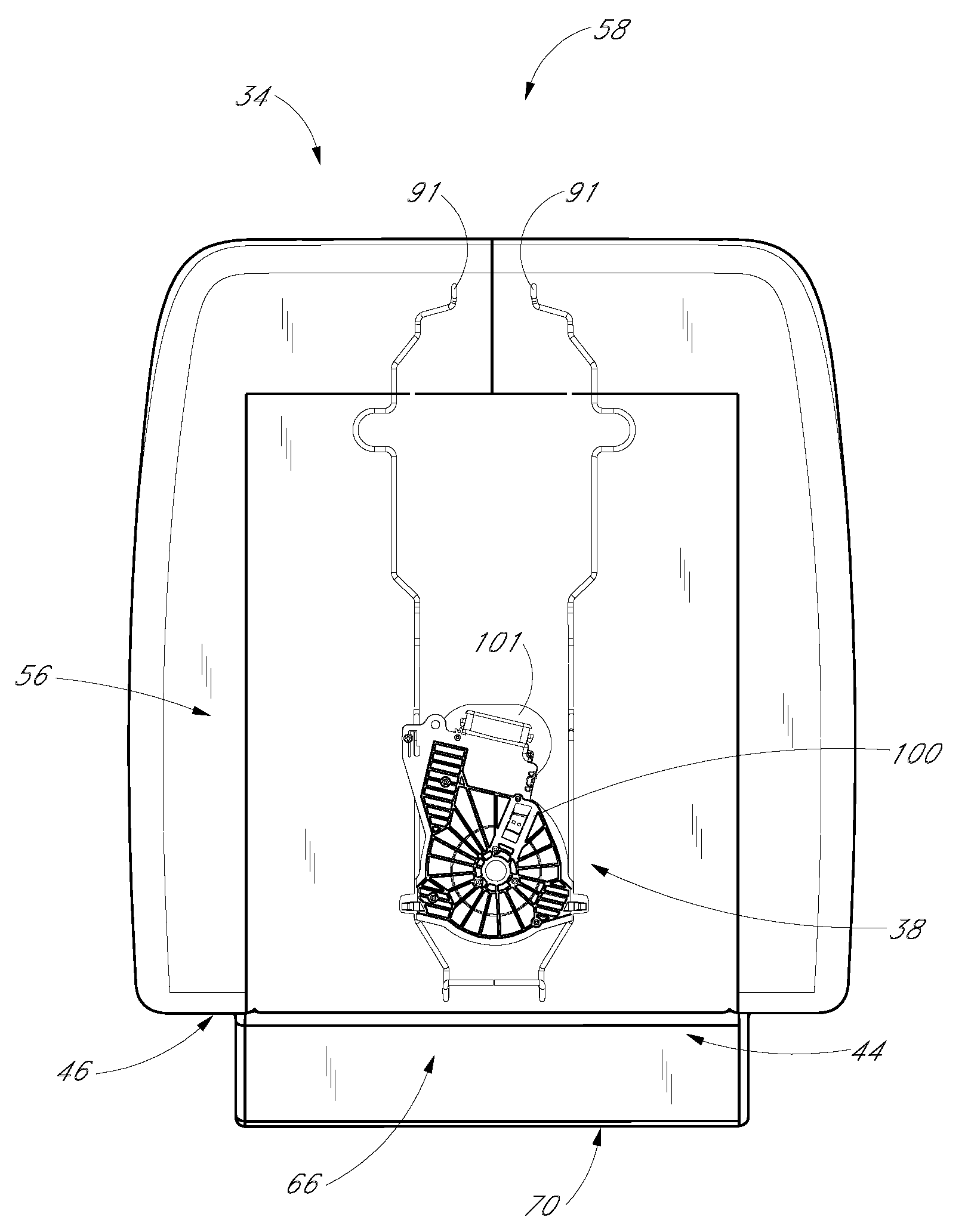
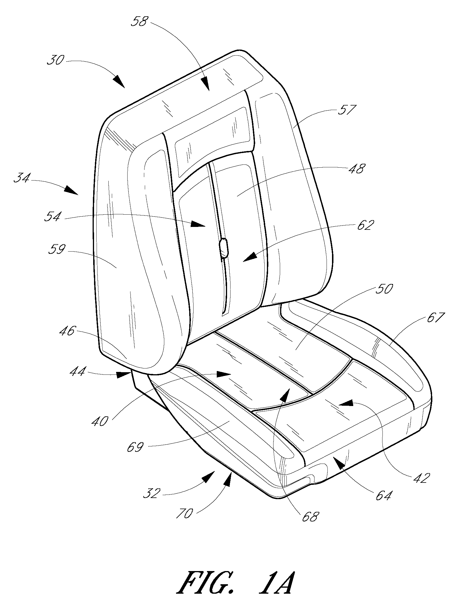
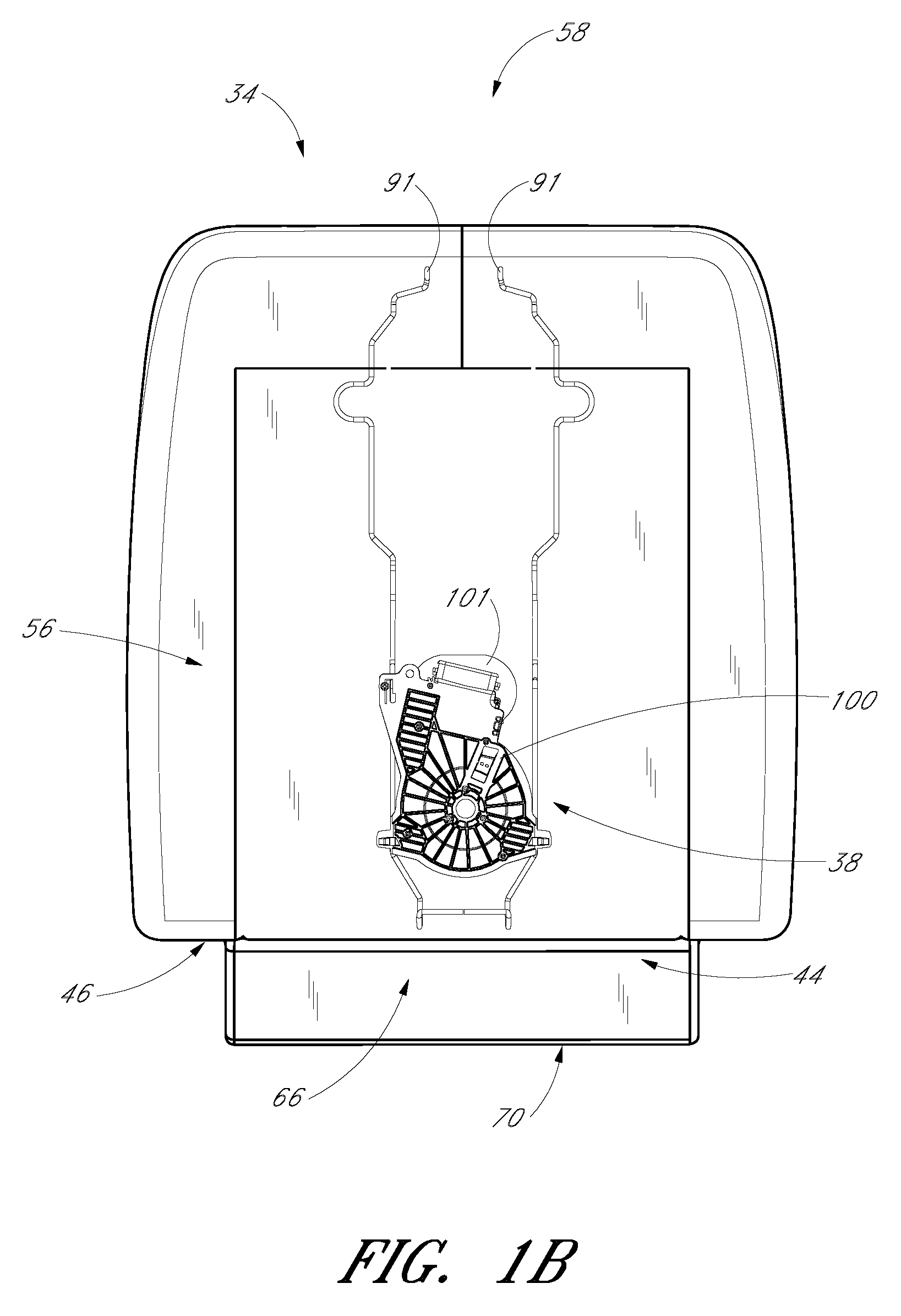
[0026]FIGS. 1A and 1B illustrate an exemplary embodiment of a seat assembly 30 with which an embodiment of a clamp may be used. The seat assembly 30 comprises a seat portion 32, a backrest portion 34, and a climate control apparatus 38, which will be described in greater detail below. When an occupant sits in the seat assembly 30, the occupant's seat is located generally in a seat area 40 of the seat portion 32 and at least a portion of their legs are supported by a thigh area 42 of the seat portion 32. In this embodiment, a rear side 44 of the seat portion 32 is coupled to a bottom side 46 of the backrest portion 34. When the occupant sits in the seat assembly 30, the occupant's back contacts the front surface 48 of the backrest portion 34 and the occupant's seat and legs contact a top surface 50 of the seat portion 32. The surfaces 48, 50 cooperate to support the occupant in a sitting position. The seat assembly 30 can be configured and sized to accommodate occupants of various si...


PUM


Abstract

A clamp that can be molded into an object comprising a first wall and a second wall spaced from the first wall. The clamp also comprises a third wall located between the first wall and the second wall. The third wall at least partially defines a first space between the first wall and the third wall. The third wall at least partially defines a second space between the second wall and the third wall. The first space is open in at least two directions, and the third wall is deflectable into the second space. The third wall is at least partially connected to the second wall along a first edge of the second wall and the second wall is connected along a second edge of the second wall to the first wall. The clamp also includes a tapered extension extending from the third wall at least partially into the first space.

Description

CROSS-REFERENCE TO RELATED APPLICATIONS[0001]This application is related to, and claims priority from, U.S. Provisional Patent Application No. 60 / 883,995, filed Jan. 8, 2007.INCORPORATION BY REFERENCE[0002]The entirety of U.S. Provisional Patent Application No. 60 / 883,995, filed Jan. 8, 2007, is expressly incorporated by reference herein and made a part of the present specification.BACKGROUND OF THE INVENTION[0003]1. Field of the Invention[0004]This invention generally relates to climate control. More specifically, this invention generally relates to a method and apparatus for installing a climate control device on a seat assembly.[0005]2. Description of the Related Art[0006]Temperature modified air for environmentally controlled living or working space is typically provided to relatively extensive areas, such as entire buildings, selected offices, or suites of rooms within a building. In the case of vehicles, such as automobiles, the entire vehicle is typically cooled or heated as ...

Claims


Application Information

Patent Timeline
IPC IPC(8): B60N2/56
CPCB60N2/56
Inventor GIFFIN, STEVEN C.
Owner AMERIGON INC
Why Eureka
Try Eureka