Adjustable antenna assembly

Inactive Publication Date: 2008-07-10
JONSA TECH
View PDF5 Cites 33 Cited by
  • Summary
  • Abstract
  • Description
  • Claims
  • Application Information

AI Technical Summary

Benefits of technology

[0015]The main objective of the present invention is to provide an adjustable

Problems solved by technology

This will increase the cost of manufacturing the antenna bracket (61) and the adjusting bracket (62).
2. Since a welding process is necessary for combining the connecting plate (633) with the connecting shaft (632), this will

Method used


Image

  • Adjustable antenna assembly
  • Adjustable antenna assembly
  • Adjustable antenna assembly

Examples


Example

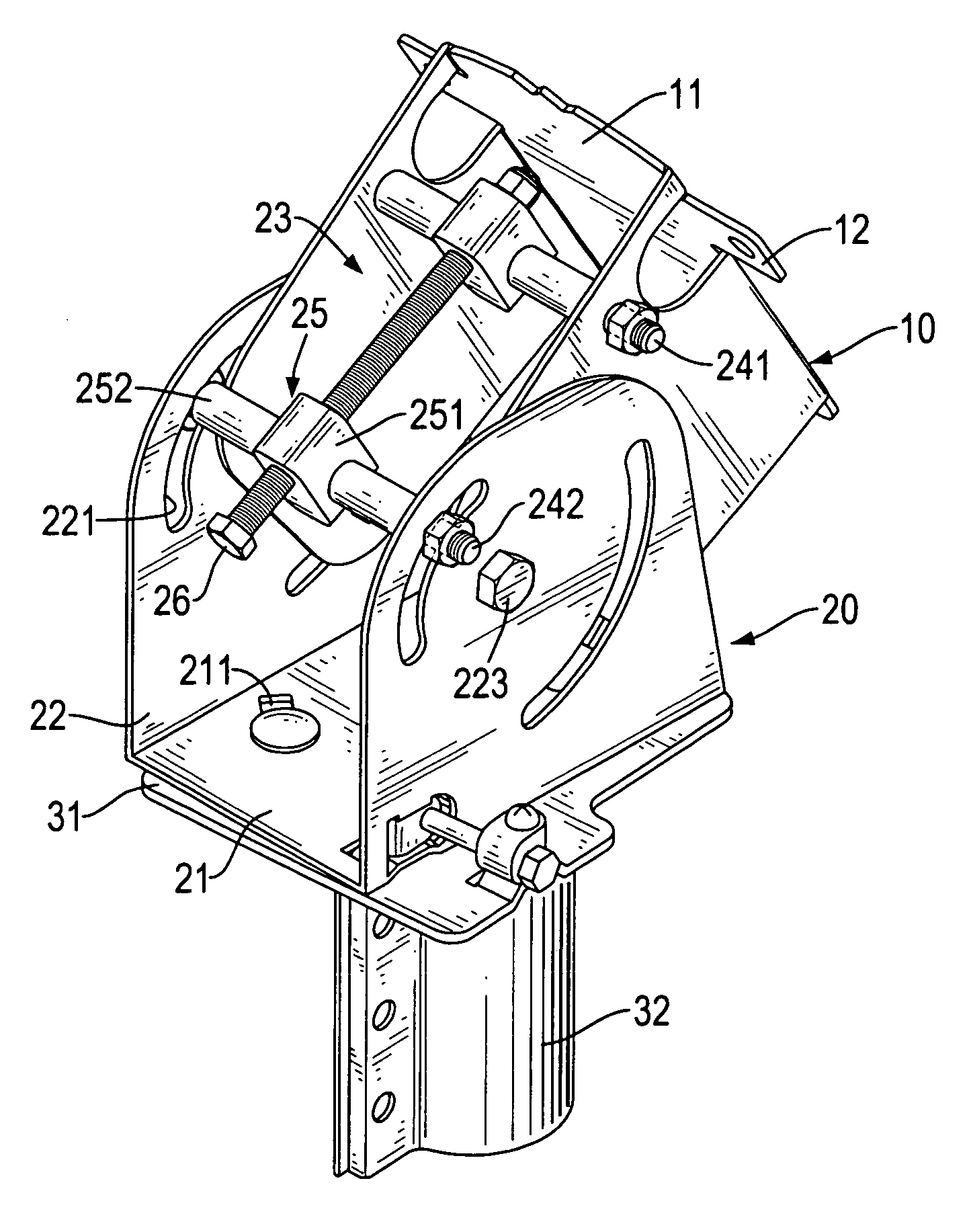
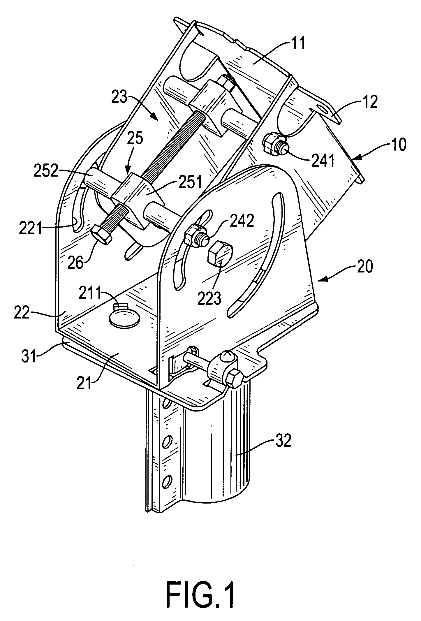
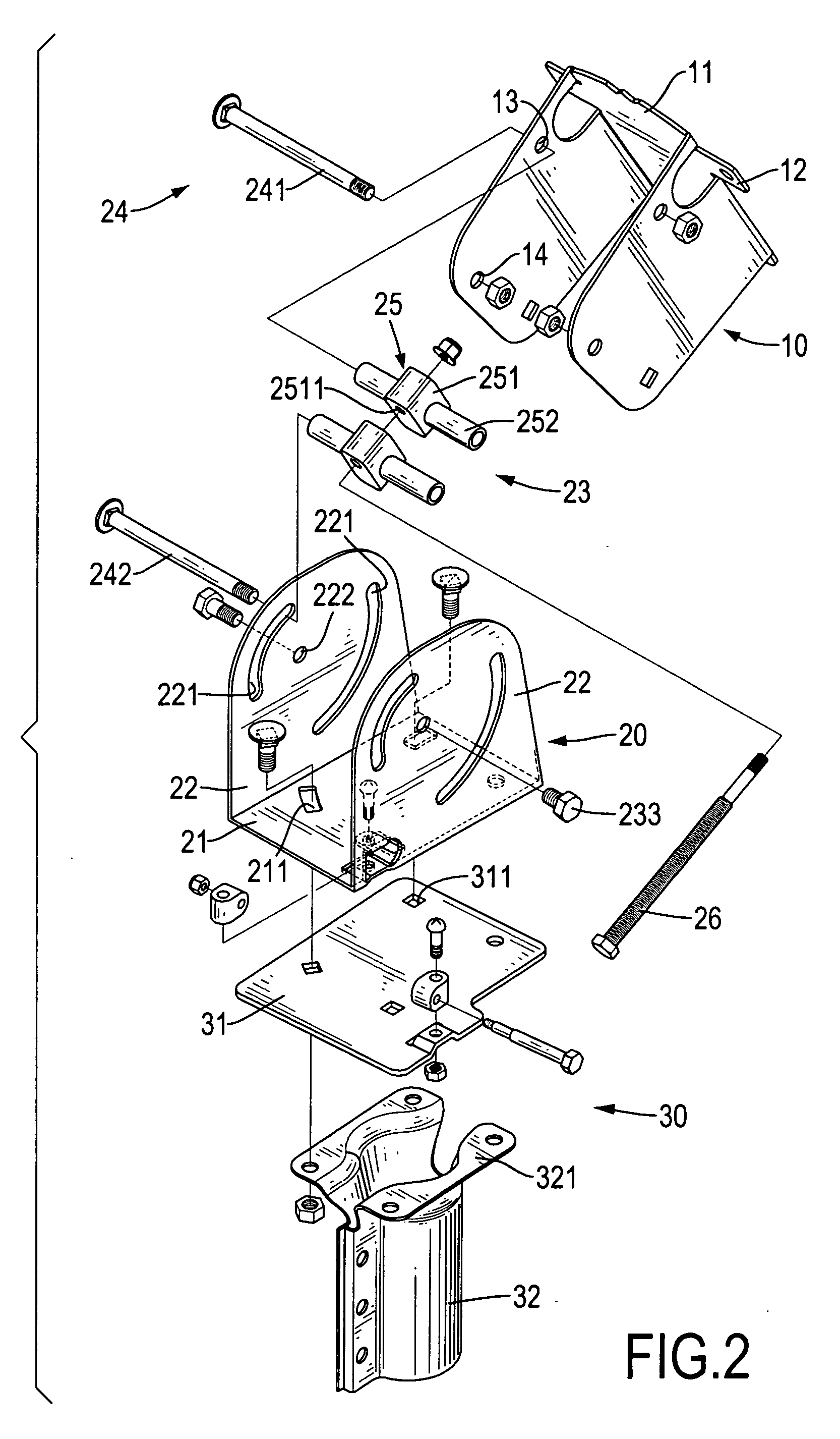
[0023]With reference to FIGS. 1, 2 and 3, an adjustable antenna assembly in accordance with the present invention comprises an antenna bracket (10), an adjusting bracket (20) and a supporting bracket (30).

[0024]The antenna bracket (10) is U-shaped, is used to connect with an antenna dish and has a face (11) and two sidewalls. The face (11) of the antenna bracket (10) is connected to a rear face of the antenna dish and has multiple wings (12). The wings (12) are formed on and laterally extend from the face (11) and are adapted to connect with the rear face of the antenna dish.

[0025]The sidewalls are mounted on the face (11) to form a U-shaped antenna bracket (10), correspond respectively to the wings (12) and each sidewall has a connecting hole (14) and a mounting hole (13). The connecting hole (14) is formed through the sidewall far away a corresponding wing (12). The mounting hole (13) is formed through the sidewall between the corresponding wing (12) and the connecting hole (14).

[...


PUM


Abstract

An adjustable antenna assembly has an antenna bracket, an adjusting bracket and a supporting bracket. The antenna bracket has a face and two sidewalls mounted on the face. The adjusting bracket is connected pivotally to the antenna bracket and has a fixed board, two elevation boards and an adjusting device. The elevation boards are mounted on the sides of the fixed board. The adjusting device is attached to the antenna bracket and the elevation boards and has a mounting device, two mounting brackets and an adjusting post. The supporting bracket is connected to the adjusting bracket and has a connecting board and a connecting shaft. The connecting board is attached to the fixed board. The connecting shaft is a single piece and is connected to the connecting board with a connecting plate.

Description

BACKGROUND OF THE INVENTION[0001]1. Field of the Invention[0002]The present invention relates to an adjustable antenna assembly, and more particularly to an adjustable antenna assembly to adjust a satellite antenna in signal-receiving angle.[0003]2. Description of Related Art[0004]To receive satellite signals such as video, telephone or the like, a satellite antenna is applied to receive and transmit signals from and to a satellite.[0005]With reference to FIGS. 4 and 5, a satellite antenna has a concave antenna dish with a rear surface and is generally mounted on a conventional adjustable antenna assembly (60). The conventional adjustable antenna assembly (60) substantially comprises an antenna bracket (61), an adjusting bracket (62) and a supporting bracket (63).[0006]The antenna bracket (61) is U-shaped, is attached to the rear surface of the antenna dish and has two sidewalls.[0007]The adjusting bracket (62) is U-shaped, is connected pivotally to the antenna bracket (61) and has ...

Claims


Application Information

Patent Timeline
IPC IPC(8): H01Q3/02
CPCH01Q1/125
Inventor PAN, TIEN-CHIH
Owner JONSA TECH
Why Eureka
Try Eureka