Method and device for compensating for thermal decay in a magnetic storage device

a magnetic storage device and thermal decay technology, applied in the field of magnetization and thermal decay, can solve the problems of process not taking into account the continuing effect of thermal decay in the process of recording data loss of undesirable magnitude, and progressive loss of amplitude of recorded data on the magnetic dis

Inactive Publication Date: 2008-07-10
SEAGATE TECH LLC
View PDF9 Cites 13 Cited by
  • Summary
  • Abstract
  • Description
  • Claims
  • Application Information

AI Technical Summary

Problems solved by technology

With respect to data stored on the magnetic disc for relatively large periods of time, thermal decay of the magnetic disc may eventually result in data loss of an undesirable magnitude.
Thermal decay results in a progressive loss of amplitude of recorded data on the magnetic disc.
However, this process did not take into account thermal decay that would continue after the test process was complete.
Thus, the unaccounted for thermal decay can cause errors in the fly-height adjustment that can result in an increased risk of failure of the magnetic data storage device.
Errors in the fly-height can be due to environmental changes such as altitude changes or temperature changes.
If the characteristics of the calibration track change due to thermal decay, a measurement, such as the EQNM measurement, may have errors.
Therefore, any adjustments to the drive, such as the fly-height adjustments, may also contain errors and cause the disc drive to fail.
For example, if the EQNM measurement is wrong, then the drive may provide a wrong adjustment for the fly-height and cause the head to contact the disc, which may lead to failure of the disc drive.
This may cause the head to contact the disc and may lead to failure of the disc drive.
If the thermal decay occurs over time, the incorrect EQNM measurement will cause the head 118 to fly closer to the disc 108 over time and may cause the head to contact (i.e. crash) the disc before the useful life of drive is complete.
This will result in a calibration track that does not have significant effective thermal decay.
This will provide a stable calibration track that will not have significant effective thermal decay that adds error to the EQNM measurement.
Additionally, the illustrations are merely representational and may not be drawn to scale.

Method used


Image

  • Method and device for compensating for thermal decay in a magnetic storage device
  • Method and device for compensating for thermal decay in a magnetic storage device
  • Method and device for compensating for thermal decay in a magnetic storage device

Examples


Embodiment Construction

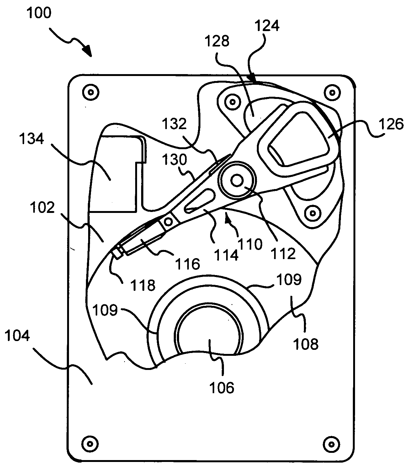
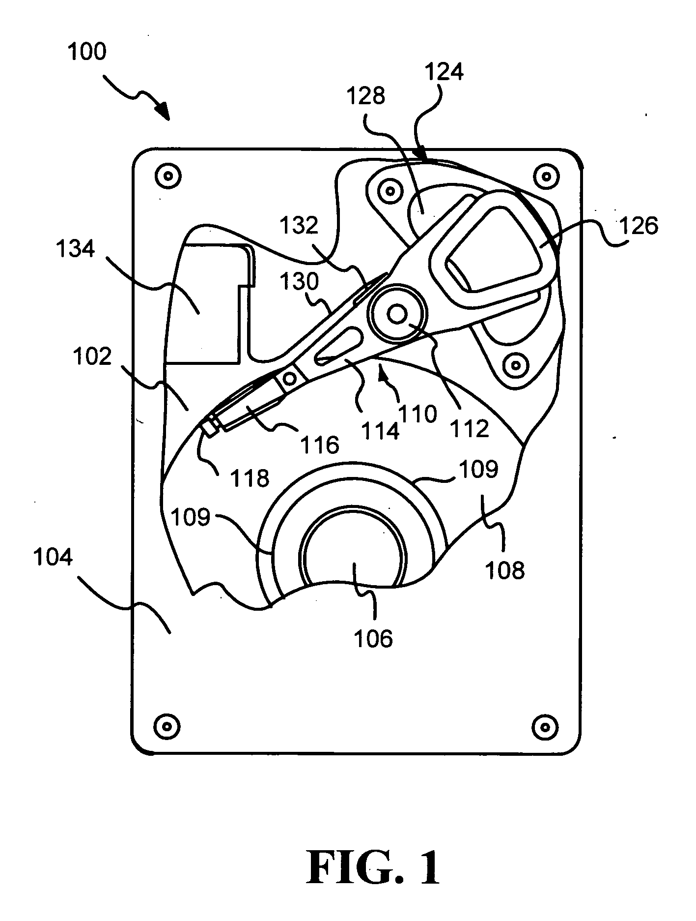
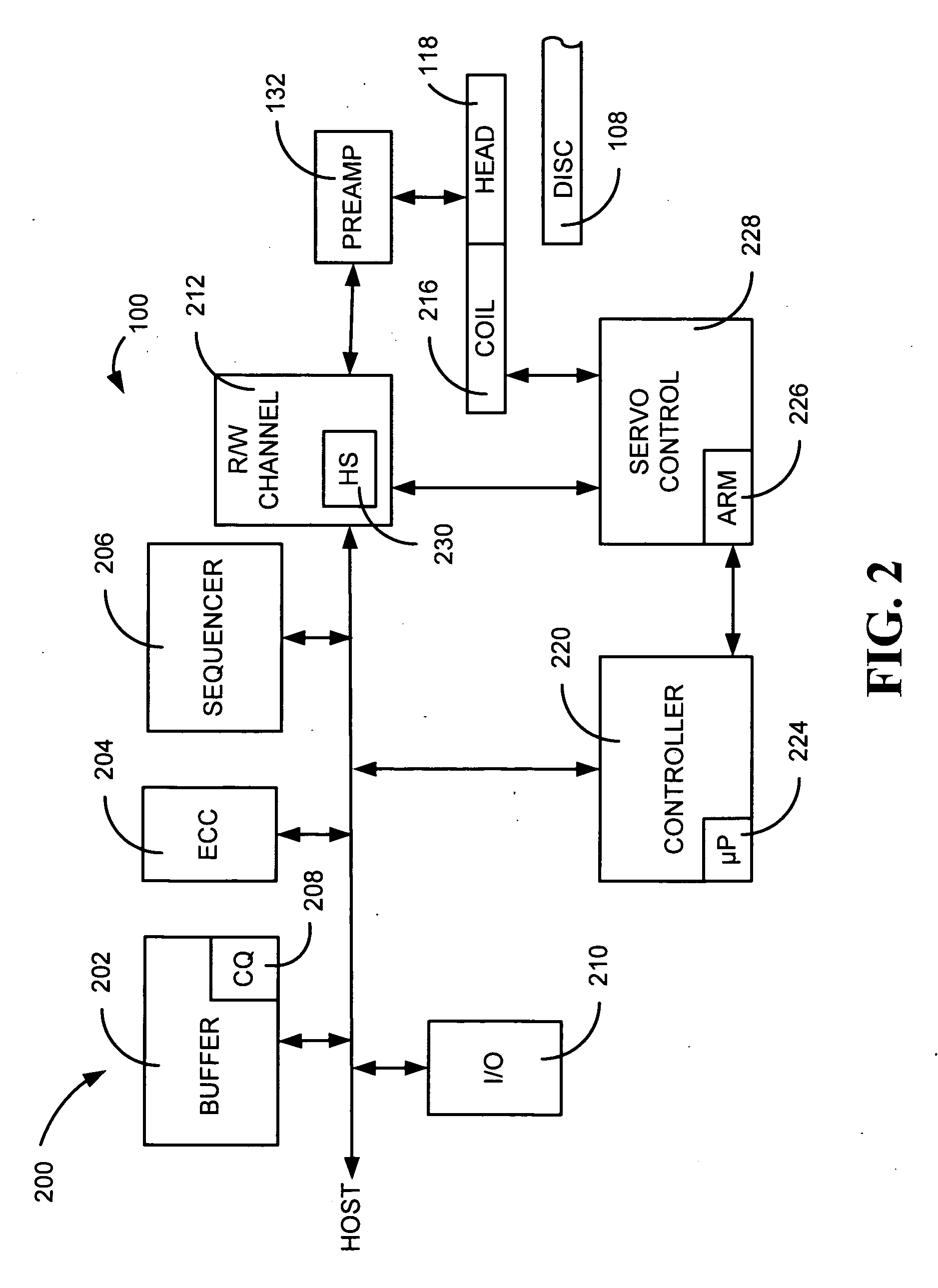
[0009]In the following detailed description of the embodiments, reference is made to the accompanying drawings which form a part hereof, and in which are shown by way of illustration of specific embodiments. It is to be understood that other embodiments may be utilized and structural changes may be made without departing from the scope of the present invention.

[0010]In a particular embodiment, the present disclosure is directed to a method including reading a calibration track on a magnetic data storage medium to obtain a first measurement of a track characteristic. The method also includes overwriting the calibration track with a first specific data pattern and reading the calibration track to obtain a second measurement of the track characteristic. The method also includes determining whether a thermal decay rate of the calibration track is acceptable based on the first measurement and the second measurement.

[0011]In another embodiment, the present disclosure is directed to a comp...


PUM

PropertyMeasurementUnit
thermal decay rateaaaaaaaaaa
thresholdaaaaaaaaaa
thermal decayaaaaaaaaaa

Abstract

The present disclosure is directed to systems and methods of compensating for thermal decay of a magnetic data storage medium. In a particular embodiment, the method includes reading a calibration track on a magnetic data storage medium to obtain a first measurement of a track characteristic. The method also includes overwriting the calibration track with a first specific data pattern and reading the calibration track to obtain a second measurement of the track characteristic. The method also includes determining whether a thermal decay rate of the calibration track is acceptable based on the first measurement and the second measurement.

Description

FIELD OF THE DISCLOSURE[0001]The present disclosure relates generally to magnetization and thermal decay. More specifically, the present disclosure relates to compensating for thermal decay of a magnetic data storage medium.BACKGROUND[0002]After a magnetic disc is magnetized, the magnetization is dissolved slightly from thermal decay as time passes. With respect to data stored on the magnetic disc for relatively large periods of time, thermal decay of the magnetic disc may eventually result in data loss of an undesirable magnitude. Thermal decay results in a progressive loss of amplitude of recorded data on the magnetic disc.[0003]In a magnetic data storage device, the fly-height, i.e. the distance between the transducing head and the magnetic disc, may be adjusted based on baseline measurement data read from a calibration track on the magnetic disc. Previously, a calibration track was written as soon as possible after the data channel of the magnetic data storage device was optimiz...

Claims


Application Information

Patent Timeline
Patent Type & Authority Applications(United States)
IPC IPC(8): G11B5/02
CPCG11B5/5534G11B5/59688G11B5/5565
Inventor MOLINE, JERRY
Owner SEAGATE TECH LLC
Why Eureka
Try Eureka