Magnetic memory
a magnetic memory and memory technology, applied in the field of magnetic memory, can solve the problems of increasing electric power consumption, reducing cell occupancy ratio, large required current for data wiring, etc., and achieve the effect of small writing curren
- Summary
- Abstract
- Description
- Claims
- Application Information
AI Technical Summary
Benefits of technology
Problems solved by technology
Method used
Image
Examples
first embodiment
[0099]A magnetic memory according to the first embodiment of the present invention will be described referring to the accompanying drawings.
[0100]In the present embodiment, in the two-axis writing method, a writing current is decreased by not using a current induced magnetic field using two wiring lines but using a current induced magnetic field using a single wiring line and using an effective magnetic field (a Rashba magnetic field: described later) based on a spin orbit interaction.
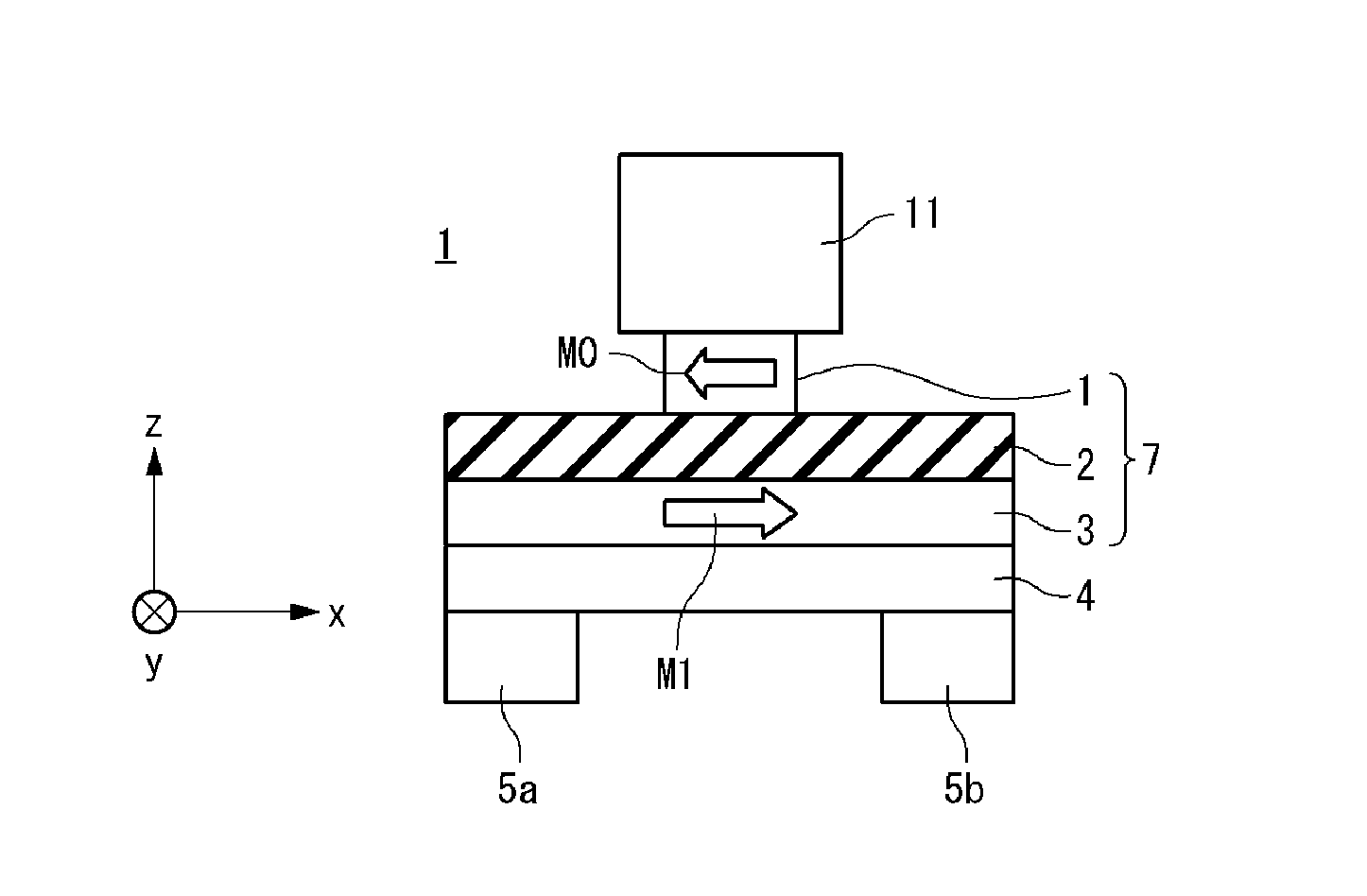
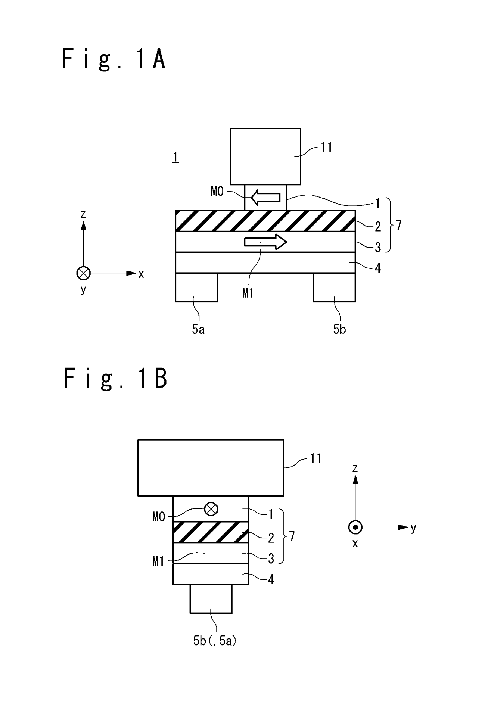
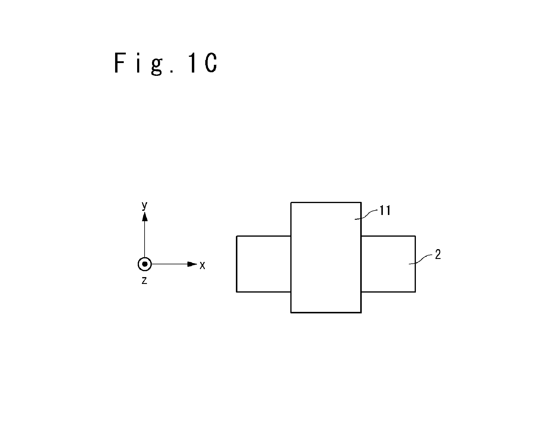
[0101]First, a configuration of a magnetic memory element of the magnetic memory according to the first embodiment of the present invention will be described. FIGS. 1A to 1C are an elevation view, a side view and a plane view showing the configuration of the magnetic memory element according to the first embodiment of the present invention. The magnetic memory element 9 includes a base layer 4, a magnetization free layer 3, a barrier layer 2, a magnetization reference layer 1, an upper electrode 11 and...
second embodiment
[0130]The magnetic memory according to the second embodiment of the present invention will be described referring to the attached drawings.
[0131]The present embodiment is different from the first embodiment in the point that the magnetization reference layer 1 and the magnetization free layer 3 have perpendicular magnetic anisotropy in the present invention while they have in-plane magnetic anisotropy in the first embodiment. The different point from the first embodiment will be mainly described below.
[0132]First, the magnetic memory element of the magnetic memory according to the second embodiment of the present invention will be described. FIGS. 8A to 8C are an elevation view, a side view and a plane view showing a configuration of the magnetic memory element according to the second embodiment of the present invention. The magnetic memory element 9a includes a base layer 4, a magnetization free layer 3, a barrier layer 2, a magnetization reference layer 1, an upper electrode 11, l...
third embodiment
[0145]The magnetic memory cell according to the third embodiment of the present invention will be described referring to the attached drawings.
[0146]In the present embodiment, in the one-axis writing method, a writing current is reduced by not using a current induced magnetic field by a single wiring line but mainly using an effective magnetic field (the Rashba magnetic field: described later) based on the spin orbit interaction. That is, the present embodiment is different from the first embodiment in the point that the current induced magnetic field generated by the current flowing in the upper electrode (the bit line) is not used for the data writing. The different point from the first embodiment will be mainly described below.
[0147]First, a configuration of the magnetic memory element of the magnetic memory according to the third embodiment of the present invention will be described. FIGS. 11A to 11C are an elevation view, a side view and a plane view showing the configuration o...
PUM
 Abstract
Description
Claims
Application Information
 - R&D
- Intellectual Property
- Life Sciences
- Materials
- Tech Scout
- Unparalleled Data Quality
- Higher Quality Content
- 60% Fewer Hallucinations
Browse by: Latest US Patents, China's latest patents, Technical Efficacy Thesaurus, Application Domain, Technology Topic, Popular Technical Reports.
© 2025 PatSnap. All rights reserved.Legal|Privacy policy|Modern Slavery Act Transparency Statement|Sitemap|About US| Contact US: help@patsnap.com


