Overlapping surround roll for loudspeaker

a loudspeaker and surround roll technology, applied in the field of electrical transducers, can solve the problems of reducing the strength and power handling capabilities of the motor of fig. 2, versus those of the motor of fig. 1, and simply having the capability to produce low frequencies insufficient, and a significant cos

Inactive Publication Date: 2008-07-10
STILES ENRIQUE M +1
View PDF4 Cites 30 Cited by
  • Summary
  • Abstract
  • Description
  • Claims
  • Application Information

AI Technical Summary

Problems solved by technology

Unfortunately, this comes at a significant cost.
This reduces the strength and the power handling capabilities of the motor of FIG. 2, versus those of the motor of FIG. 1.
But simply having adequate volume displacement capability to produce low frequencies is not enough.
Within the limitations of a fixed size frame (or cabinet), increasing the size of a conventional single roll surround has meant either (a) making the surround wider, which reduces the diameter of the inner portion of the surround which couples to the diaphragm, which in turn reduces the voice coil diameter and size of the magnet, resulting in a weaker motor, or (b) making the surround taller, which makes the surround stiffer, which raises the resonant frequency and reduces the low end response of the speaker.

Method used


Image

  • Overlapping surround roll for loudspeaker
  • Overlapping surround roll for loudspeaker
  • Overlapping surround roll for loudspeaker

Examples


Embodiment Construction

[0025]The invention will be understood more fully from the detailed description given below and from the accompanying drawings of embodiments of the invention which, however, should not be taken to limit the invention to the specific embodiments described, but are for explanation and understanding only.

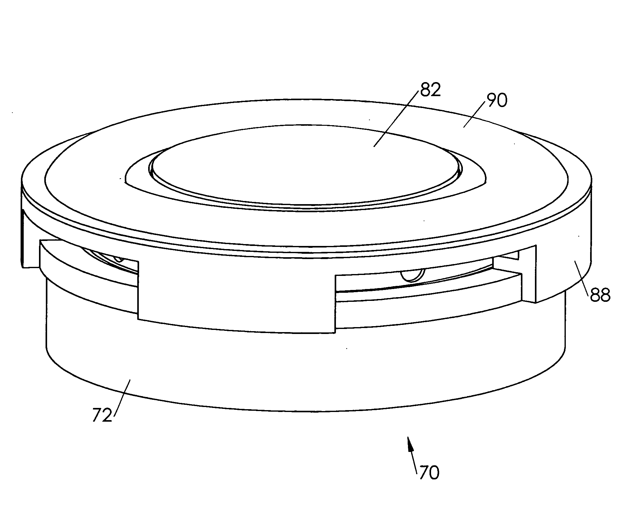
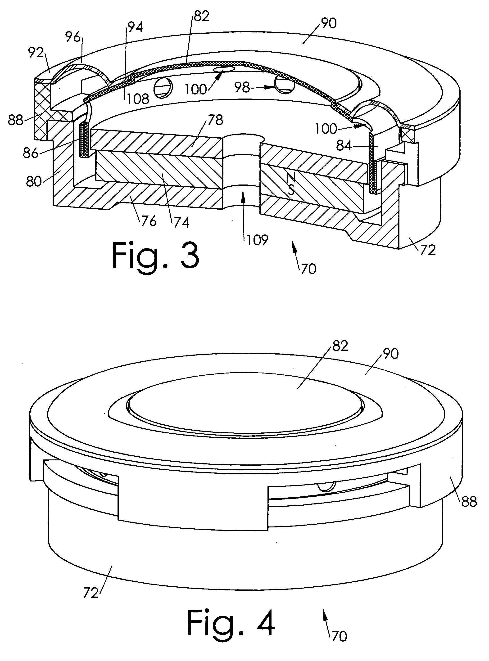
[0026]FIGS. 3-4 illustrate a loudspeaker 70 according to one embodiment of this invention. The loudspeaker includes an internal magnet geometry motor having a cup yoke 72, an internal magnet 74 magnetically coupled to the back plate portion 76 of the cup, and a top plate 78 magnetically coupled to the magnet and defining a magnetic air gap with a cylinder portion 80 of the cup. The outer perimeter of a diaphragm 82 is coupled to or integrally constructed with a bobbin 84, and a voice coil 86 is coupled to the bobbin and disposed in the magnetic air gap. A frame 88 is coupled to the cup, and a surround 90 has an outer portion 92 coupled to the frame and an inner portion 94 to a middle ...


PUM


Abstract

A loudspeaker in which the voice coil diameter is so large that the voice coil is axially beneath the suspension roll of the surround. The surround has an overlapping suspension roll such that the inner portion of the surround is coupled to the diaphragm well inward of the bobbin. Such a transducer having greatly extended low frequency abilities by virtue of its wider, softer suspension roll enabling a much lower resonant frequency, and by virtue of its maximum sized magnet and voice coil yielding increased motor strength and power handling. Additionally, the dome diaphragm can now be vented through the portion of the dome that is beneath the surround roll, releasing the trapped back pressure below the diaphragm, thereby further lowering the resonant frequency.

Description

BACKGROUND OF THE INVENTION[0001]1. Technical Field of the Invention[0002]This invention relates generally to electromagnetic transducers, and more specifically to a loudspeaker whose surround suspension component extends radially inward and attaches to the diaphragm at a point significant inward of the diaphragm's outer perimeter.[0003]2. Background Art[0004]FIG. 1 illustrates a conventional loudspeaker 10, of the “microdriver” type typically used in applications such as laptop computers, desktop computer displays, and other applications in which space is at an absolute premium and very little can be spared for housing loudspeakers.[0005]The loudspeaker includes an internal magnet geometry motor structure having a cup 12, an optional steel spacer plate 14, a permanent magnet 16, and a top plate 18 which defines a magnetic air gap with the cylindrical portion of the cup.[0006]A frame 20 is coupled to the motor structure. A dome diaphragm 22 is coupled to the frame by a surround 24 h...

Claims


Application Information

Patent Timeline
Patent Type & Authority Applications(United States)
IPC IPC(8): H04R19/02H04R1/00
CPCH04R7/24H04R2499/15H04R9/045H04R9/022
Inventor STILES, ENRIQUE M.CALDERWOOD, RICHARD C.
Owner STILES ENRIQUE M
Why Eureka
Try Eureka