Space-Time-Frequency Sensing of RF Spectrum in Cognitive Radios

a cognitive radio and space-time frequency technology, applied in the field of spectrum sensing techniques in cognitive radio (cr) communications systems, can solve problems such as the existence of pushes

Inactive Publication Date: 2008-07-10
MITSUBISHI ELECTRIC RES LAB INC
View PDF6 Cites 79 Cited by
  • Summary
  • Abstract
  • Description
  • Claims
  • Application Information

AI Technical Summary

Problems solved by technology

Consequently, “hidden” PUs can exist because a single CR cannot...

Method used


Image

  • Space-Time-Frequency Sensing of RF Spectrum in Cognitive Radios
  • Space-Time-Frequency Sensing of RF Spectrum in Cognitive Radios
  • Space-Time-Frequency Sensing of RF Spectrum in Cognitive Radios

Examples


Embodiment Construction

CR Network

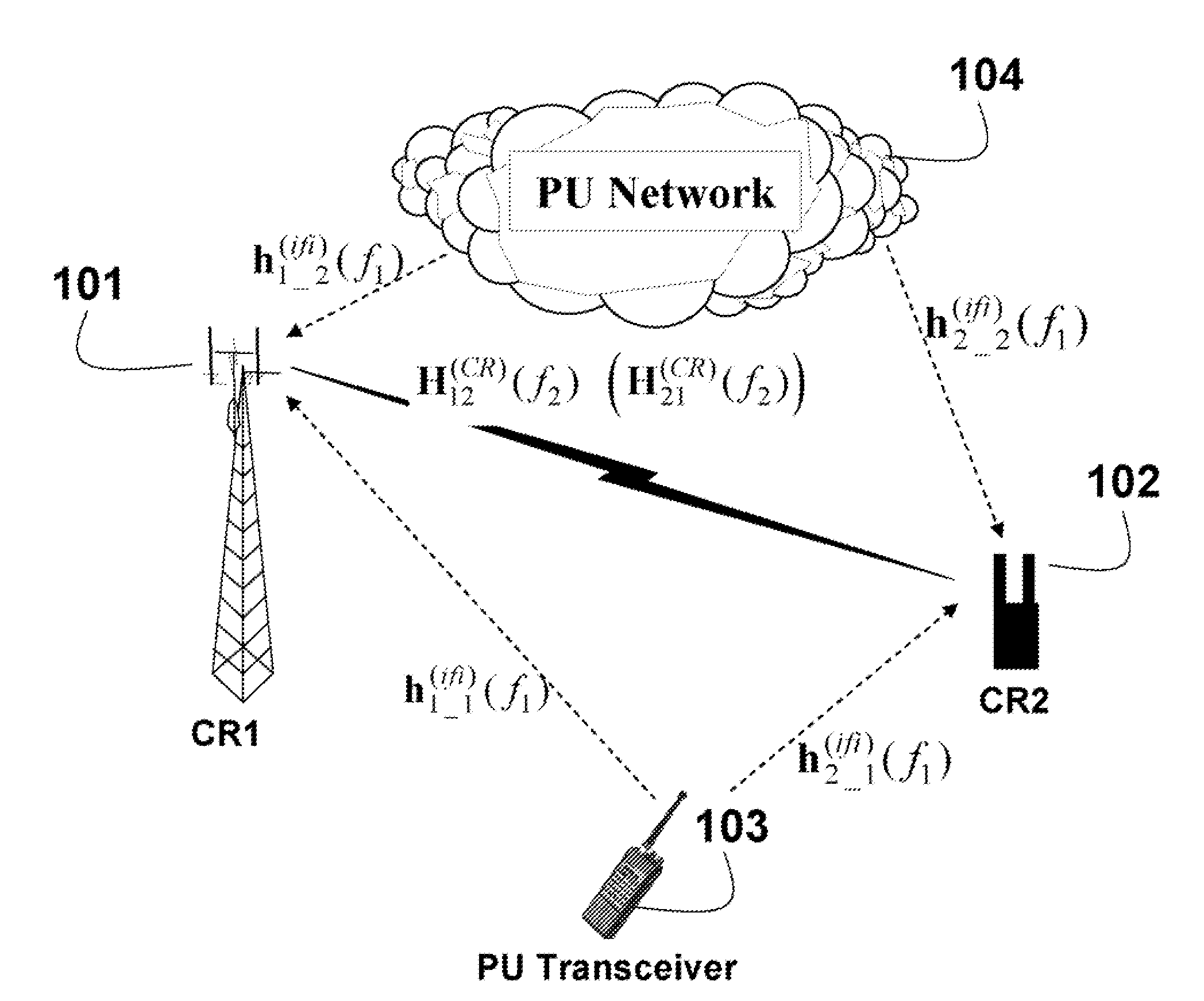
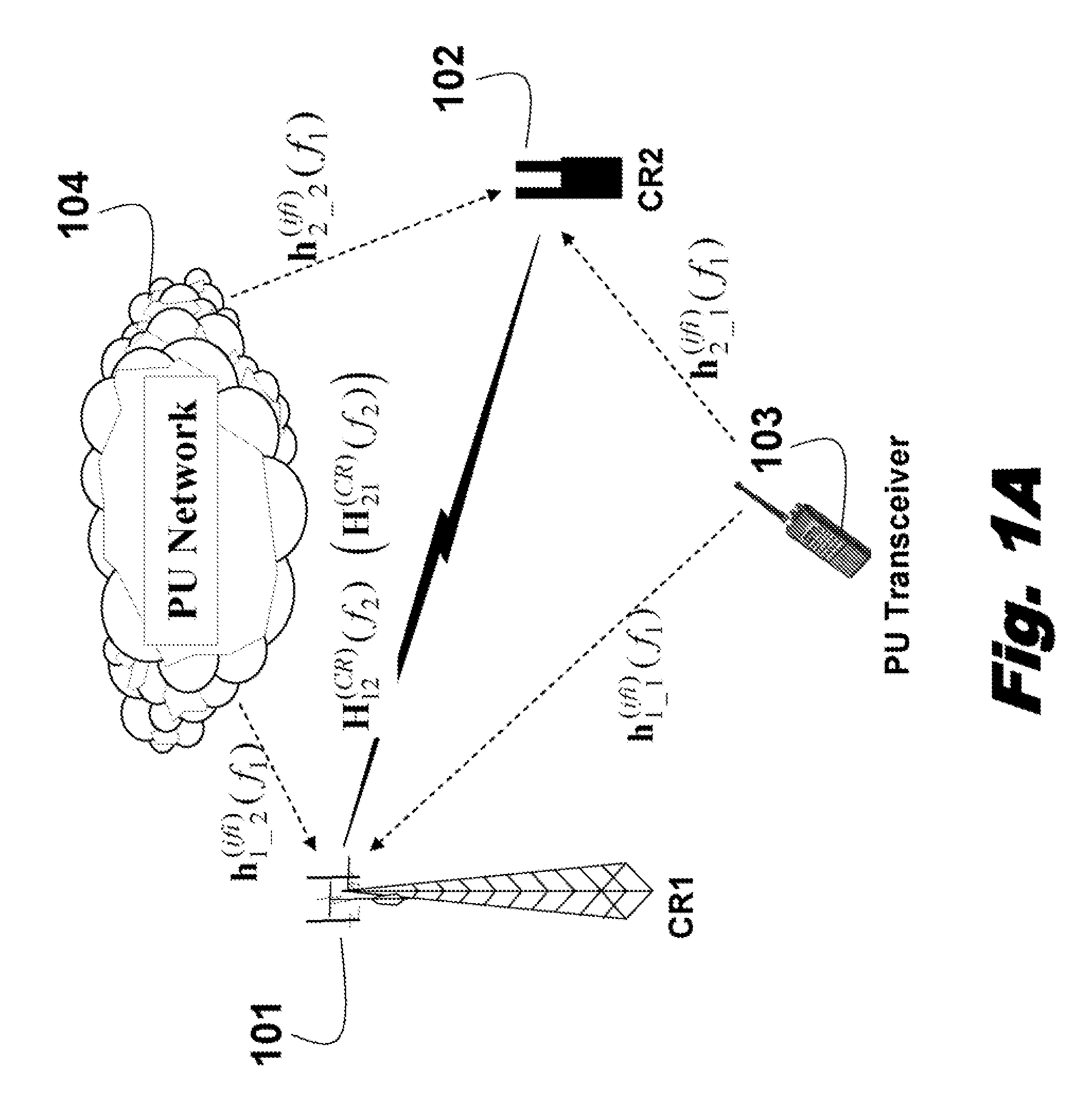
[0013]FIG. 1A shows radio networks in which the embodiments of our invention operates. The task is to detect unused frequency bands (“spectrum holes”401 in FIG. 4). The unused frequency bands can then be assigned as available frequency bands for a cognitive radio.

[0014]More specifically, we desire to detect the unused frequency bands using cognitive radios equipped with antenna arrays. As defined herein, an antenna array includes multiple antenna elements that can be individually controller over space, time and frequency dimensions.

[0015]The networks include a primary user (PU) network 104 and a PU transceiver 103, and secondary users (CR) 101-102. The PUs and CRs are located so that their signals can interfere with each other. As shown, the communication links do not need to be in the form of direct propagations, i.e., line-of-sight (LOS) connections. The embodiments of our invention can be applied to any scattering / fading environment.

[0016]As shown in FIG. 1A, two CRs (C...


PUM


Abstract

A method detects unused frequency bands in a cognitive radio network. Multiple frequency bands for RF signals are sensed using an antenna array including a plurality of elements coupled to a receive RF chain, in which the plurality of elements are individually controllable. For each frequency band, multiple spatial directions are sensed for the RF signals using the antenna array. A particular frequency band and a particular direction and a particular time slot are assigned as an available frequency band, an available direction and a particular time slot for transmitting RF signals in a cognitive radio if the RF signals are not sensed in the particular spatial direction for the particular frequency band, and in which the RF signals are transmitted by a transmit chain connected to the antenna array.

Description

FIELD OF THE INVENTION[0001]This invention relates generally to spectrum sensing techniques in cognitive radio (CR) communications systems, and more particularly to CR devices with antenna arrays.BACKGROUND OF THE INVENTION[0002]In cognitive radio techniques, secondary users (CR transceivers) dynamically change transmit and receive parameters so that their signals do not interfere with signals of primary users (PU transceivers). Conventionally, cognitive radios consider radio frequency spectrum utilization, user behavior, and network state. Cognitive radios are considered in the IEEE 802.15, IEEE 802.19, and IEEE 802.22 standards. Conventionally, cognitive radio techniques conduct one-dimensional spectrum sensing by periodically scanning only the frequency domain to locate unused frequency bands (“spectrum holes”). The unused frequency bands can then be used for CR to transmit signals that do not interfere with the signals of the PUs.[0003]To obtain accurate result, a duration T,(ƒ)...

Claims


Application Information

Patent Timeline
IPC IPC(8): H04B17/00H04J99/00H04W16/14H04W16/28H04W24/00H04W72/04H04W72/08
CPCH04L5/0062H04L27/0006H04W72/085H04W24/00H04W72/046H04W16/28H04W72/542
Inventor TEO, KOON HOOZHANG, HONGYUANNAKACHE, YVES-PAUL N.ZHANG, JINYUN
Owner MITSUBISHI ELECTRIC RES LAB INC
Why Eureka
Try Eureka