Clamp For Supporting Bar Of Components Of Conveyors Of Articles

a technology of supporting bar and supporting bar, which is applied in the direction of conveyors, couplings, rod connections, etc., can solve the problems of affecting the stability of the supporting bar, the inability to ensure the keeping of the containment/routing guide of the article, and the displacement of the bar from the horizontal position, etc., to achieve the effect of easy and precis

Active Publication Date: 2008-07-17
REXNORD FLATTOP EURO SRL
View PDF6 Cites 1 Cited by
  • Summary
  • Abstract
  • Description
  • Claims
  • Application Information

AI Technical Summary

Benefits of technology

[0012]An embodiment of the present invention proposes a solution includes providing elastic means used for the easy and precise positioning of the bar, and distinct tightening means for blocking the bar in the desired position, once the latter has been reached, an event that is made evident thanks to the elastic positioning means.

Problems solved by technology

In fact, a drawback of such solution is given by the fact that such a clamp is by its nature unsuitable to guarantee a suitable clamping of the bar, adapted to recover the inevitable plays existing between bar and the through holes in the clamp body, and therefore it does not assure that the articles containment / routing guides are kept in the desired position, as parallel as possible to the transport plane.
In fact, the action exerted by the spring is not sufficient to prevent that the existing play between the bar and the edges of the through holes causes a displacement of the bar from the horizontal position.
The bar, under its own weight and the weight of the guides mounted thereon, can in this way take an inclination (which is higher the longer the bar) that as a result causes an uncorrected alignment of the containment / routing guides.
However, this would reduce the efficacy of the clamp under the viewpoint of the bar positioning easiness: a spring that exerts an excessive pushing action against the movable body would make it very difficult, not to say impossible, to longitudinally slide the bar so as to bring one of the grooves formed thereon in correspondence of the annular projection.
In order to allow the sliding of the bar necessary to the positioning thereof, the action exerted by the spring necessarily has to be limited, and this jeopardizes the performances of the clamp in terms of bar clamping action.
Thus, even if the force exerted by the spring is increased, this can never guarantee a stable blocking of the bar.
Moreover, the use of the mentioned clamp significantly impacts on the time necessary for the adjustment of the position of the containment / routing guides.

Method used


Image

  • Clamp For Supporting Bar Of Components Of Conveyors Of Articles
  • Clamp For Supporting Bar Of Components Of Conveyors Of Articles
  • Clamp For Supporting Bar Of Components Of Conveyors Of Articles

Examples


Embodiment Construction

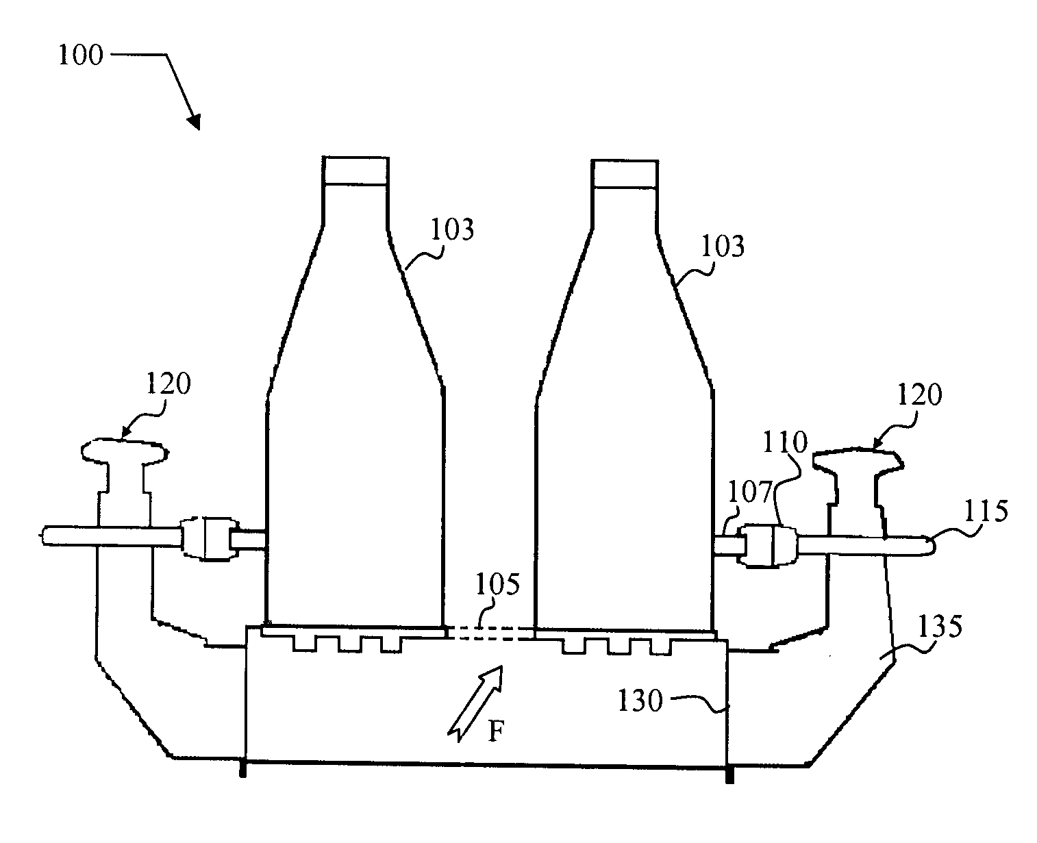
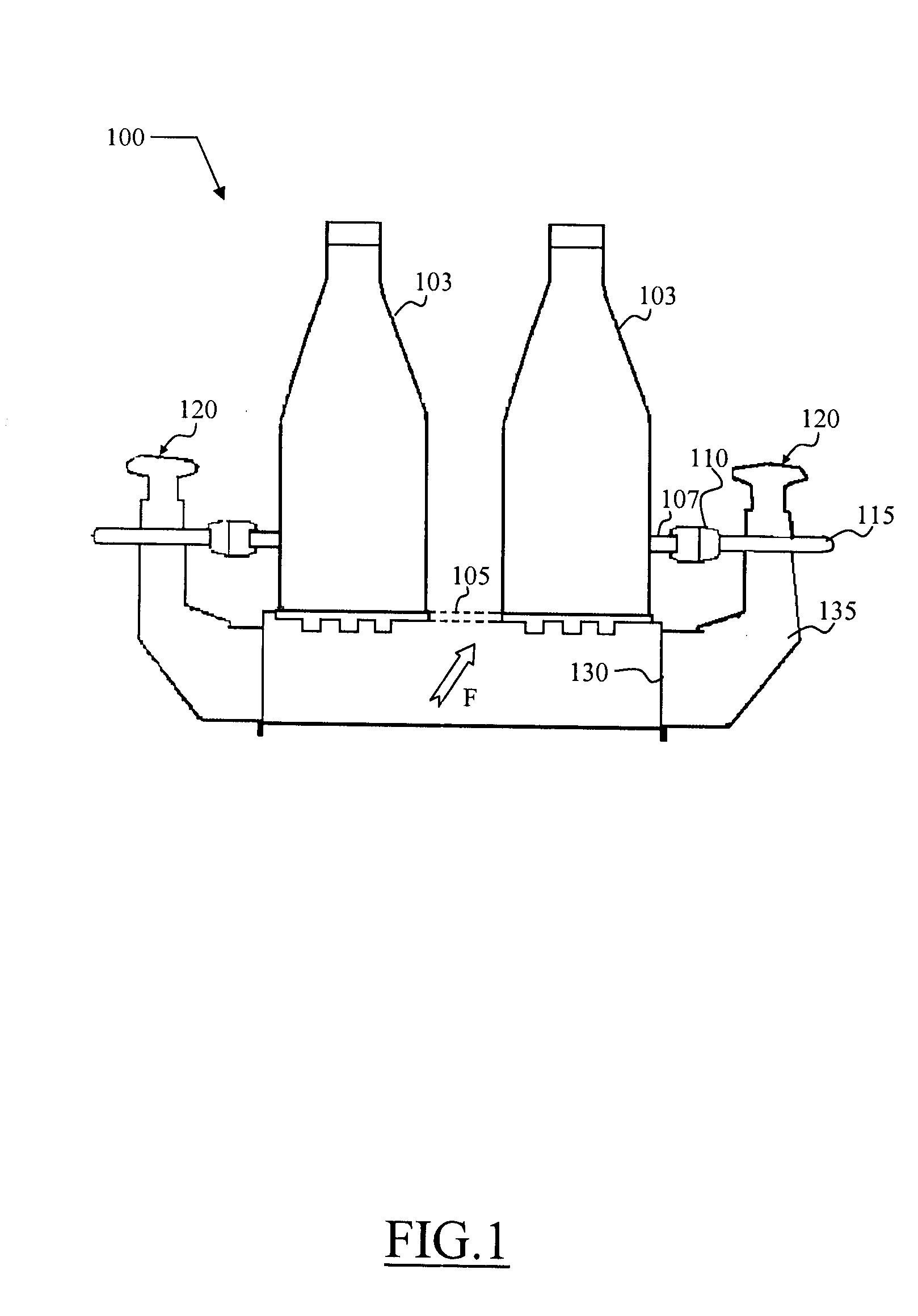
[0022]With reference to the drawings, in FIG. 1 there is schematically shown in elevation a conveyor of articles 100, for instance but not limitatively for the transport of bottled drinks in plastic bottles 103, in which a clamp according to an embodiment of the present invention is advantageously exploitable. The conveyor 100 includes a transport mat 105, for example a transport belt or a transport chain, made for instance by a succession of chain links hinged to each other so as to define a substantially plane support surface for supporting the transported articles; the transport mat 105 extends along a transport path, and is movable, in the direction of the arrow F, under the action of suitable drive means (not shown in the drawing because known per-se).

[0023]For the containment and the correct routing of the articles transported by the transport mat 105, at the two sides thereof guides 107 are provided that extend along the transport path. The guides 107, that can be static, mad...


PUM


Abstract

A clamp adapted to clamp a bar, particularly supporting components such as guides of conveyors of articles. The clamp includes: a clamp body, adapted to accommodate the support bar for supporting the components, with the possibility of adjusting the relative position of the bar with respect to the clamp by longitudinally sliding the bar; positioning means arranged to have a first working position in which the positioning means are elastically urged in abutment against the bar to engage at least positioning notch, provided on the bar, upon reaching a predetermined position, so as to essentially prevent a further longitudinal sliding of the bar once said predetermined position is reached. The clamp further includes tightening means, distinct from said positioning means and adapted in use to hold the bar in position against displacements with respect to the clamp body.

Description

CROSS REFERENCES TO RELATED APPLICATIONS[0001]This application claims the priority benefit of Italian patent application, IT M12007A000031, filed on Jan. 11, 2007.STATEMENT REGARDING FEDERALLY SPONSORED RESEARCH[0002]Not ApplicableTECHNICAL FIELD[0003]The present invention relates to a clamp of the type employed in conveyors of articles for supporting the components thereof.DESCRIPTION OF THE BACKGROUND ART[0004]Clamps of the above mentioned type are used in conveyors of articles, for instance in belt or chain conveyors, for supporting components thereof, such as guides for the containment / routing of the transported articles.[0005]In such applications, the clamps normally sustain a respective bar (for example a steel rod) intended in turn to support guide-holding elements of the guide for the containment / routing of the articles. The bar has, mounted on one end thereof (also referred to as the head), a guide-holding element, and the bar is clamped by the clamp, with the possibility o...

Claims


Application Information

Patent Timeline
Patent Type & Authority Applications(United States)
IPC IPC(8): B25B5/10
CPCB65G21/2072F16B2/065Y10T403/7194Y10T24/44017Y10T403/32483Y10T403/3961Y10T403/51
Inventor ANDREOLI, ANDREA
Owner REXNORD FLATTOP EURO SRL
Why Eureka
Try Eureka