
job plan display system

A technology of operation planning and display system, applied in general control systems, control/regulation systems, computer control, etc., can solve problems such as system load increase, suppress the increase in system load, improve operability or work efficiency Effect

Active Publication Date: 2018-01-02
TOYOTA JIDOSHA KK
View PDF6 Cites 0 Cited by
  • Summary
  • Abstract
  • Description
  • Claims
  • Application Information

AI Technical Summary

Problems solved by technology

[0008] However, in the prior art disclosed in Patent Document 1, if the design data (CAD data) of each part is saved or updated, the thumbnails of the parts will also be updated or replaced in accordance with the saving or updating. Problems such as increased system load, or problems such as parts thumbnails being updated or replaced based on CAD data initially created by designers of CAD data for research, etc.
[0009] In addition, in the prior art disclosed in Patent Document 1, if the changed position of the design data (CAD data) of each part does not appear in the thumbnail, the thumbnail of the part will follow the design regardless of whether data update is originally required. Or the design data is updated or replaced, so there may be a problem that the system load will further increase

Method used


Image

  • job plan display system
  • job plan display system
  • job plan display system

Examples


Embodiment approach 1

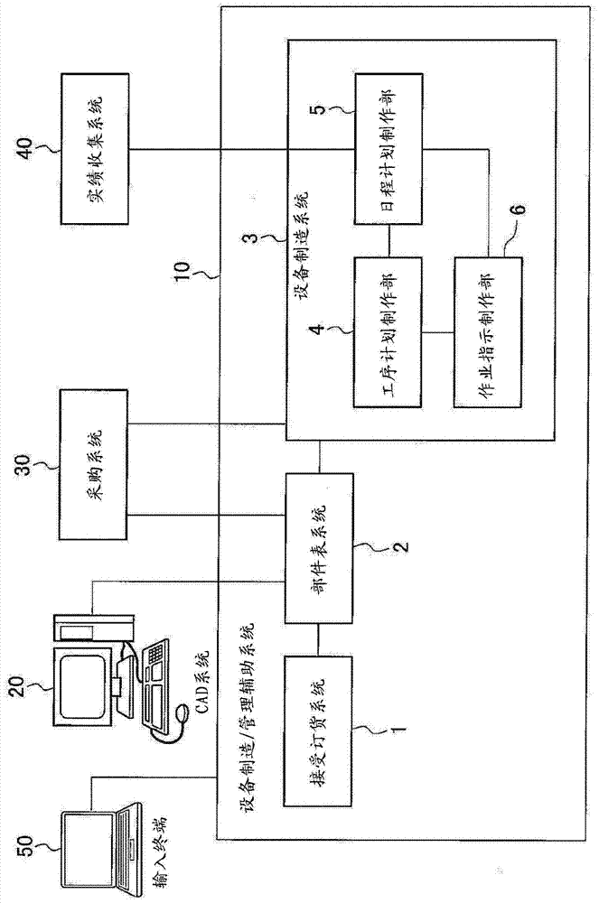
[0030] figure 1 It is a basic configuration diagram showing the basic configuration of the facility manufacturing / management support system according to the first embodiment to which the work plan display system of the present invention is applied. Here, the equipment manufacturing / management support system 10, for example, cooperates with the CAD system 20, the procurement system 30, and the performance collection system 40, etc., in which the CAD system 20 assists in the production of equipment and machinery, and the management of production. , the design data (CAD data) of the machine or its constituent parts, the procurement system 30 creates procurement data on the order and purchase of materials and parts to be used, and the performance collection system 40 summarizes the start, completion, Actual performance data about the work, such as the required work time and the operator in charge of the work. In addition, the facility manufacturing / management support system 10 is...

Embodiment approach 2

[0046] Figure 5 It is a flowchart explaining the flow of display processing performed by the second embodiment of the work plan display system (schedule creation unit 5 ) of the present invention. In this second embodiment, instead of the intention of the designer who created the CAD data, it is determined based on the preset update time whether to display or update the thumbnails in the "job bar". same. Therefore, the same reference numerals are assigned to the same components as those in Embodiment 1, and detailed description thereof will be omitted.

[0047] like Figure 5 As shown, the schedule preparation unit 5 of the second embodiment first creates an operation plan for each numerically controlled machine tool based on information transmitted from the parts list system 2, the procurement system 30, the performance collection system 40, etc., as in the above-mentioned first embodiment ( STEP 100), this operation plan is constituted by a plurality of unit operations, ...

Embodiment approach 3

[0054] Image 6 It is a basic configuration diagram showing the basic configuration of an equipment manufacturing / management support system according to Embodiment 3 of the work plan display system (schedule creation unit 5) of the present invention, Figure 7 is explained by Image 6 The flow chart of the flow of display processing performed by the schedule creation unit is shown. In this third embodiment, instead of the intention of the designer who created the CAD data or the preset update time, it is determined whether to display or update the thumbnails in the "work bar" based on the progress information of design data creation, and other The configuration is almost the same as that of Embodiment 1 and Embodiment 2 described above. Therefore, the same reference numerals are assigned to the same components as those in Embodiment 1 and Embodiment 2, and detailed description thereof will be omitted.

[0055] like Image 6 As shown, the equipment manufacturing / management ...


PUM


Abstract

The present invention provides a work plan display system that displays a work plan for a product, and displays a thumbnail as image information of the product on the display area of ​​the work plan based on the design data of the product, thereby suppressing an increase in system load And display the appropriate thumbnail. This work plan display system is based on the intention of the designer who created the design data given to the product design data, the preset update time, the progress information of the design data creation, and the change position of the design data when the design data is changed. At least one of the relationship with the coordinates of the viewpoint when creating the thumbnail is used to determine whether to display or update the thumbnail on the display area of ​​the job plan.

Description

technical field [0001] The present invention relates to an operation plan display system, for example, relates to an operation plan display system for displaying an operation plan of a numerically controlled operation performed by a numerically controlled machine tool in the manufacturing process of production equipment. Background technique [0002] Conventionally, production facilities for manufacturing various parts (for example, motors, batteries, semiconductors, etc.) used in automobiles, for example, have independently manufactured a plurality of parts constituting the production facility by NC (Numerical Control: Numerical Control) machine tools. Component parts, and these multiple component parts are combined to produce. [0003] In recent years, in order to manufacture components of such production equipment, a plurality of CNC machine tools are arranged in a plurality of processing lines, and the operation status of the CNC machine tools arranged in these processin...

Claims


Application Information

Patent Timeline
Patent Type & Authority Patents(China)
IPC IPC(8): G05B19/4097
CPCG05B19/4097G05B2219/32128G05B19/418Y02P90/02G05B2219/35012
Inventor 斋藤彻田上英行安间誉井藤胜弘
Owner TOYOTA JIDOSHA KK
Learn More