
Magazine Assembly for Presenting a Pressure Cartridge to a Compressed Gas Powered Device

a technology of compressed gas and pressure cartridge, which is applied in the direction of compressed gas guns, white arms/cold weapons, weapons, etc., can solve the problems of reducing the firing capacity of the firearm, affecting the firing effect of the gas cartridge and/or the firearm,

Active Publication Date: 2008-07-17
CROSMAN CORP
View PDF58 Cites 10 Cited by
  • Summary
  • Abstract
  • Description
  • Claims
  • Application Information

AI Technical Summary

Benefits of technology

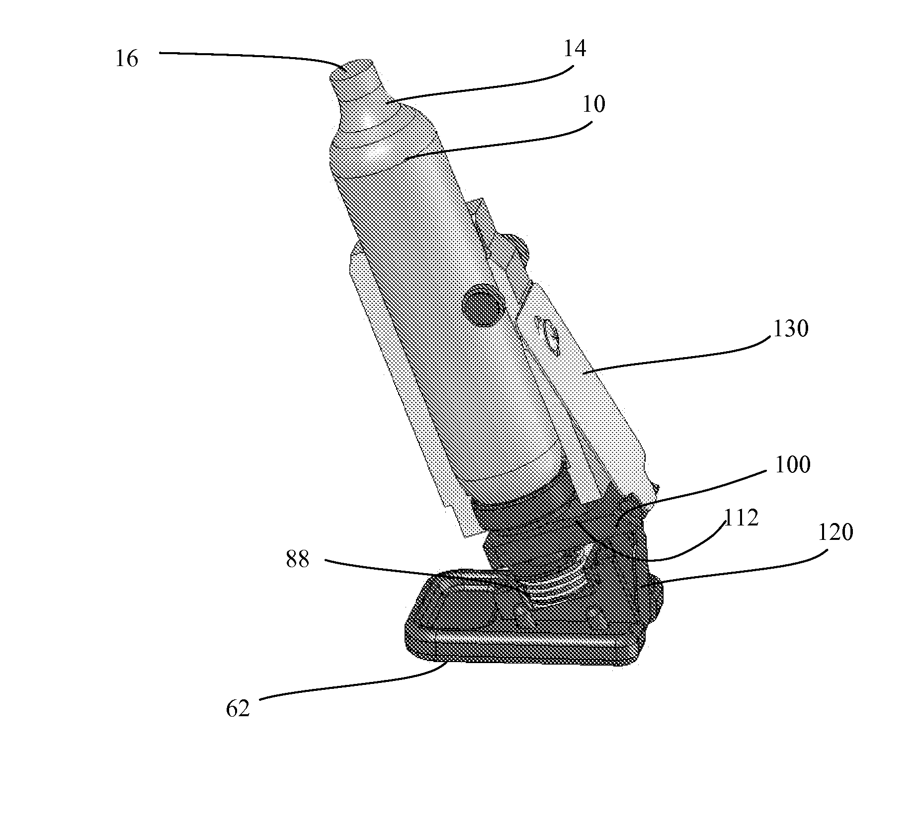
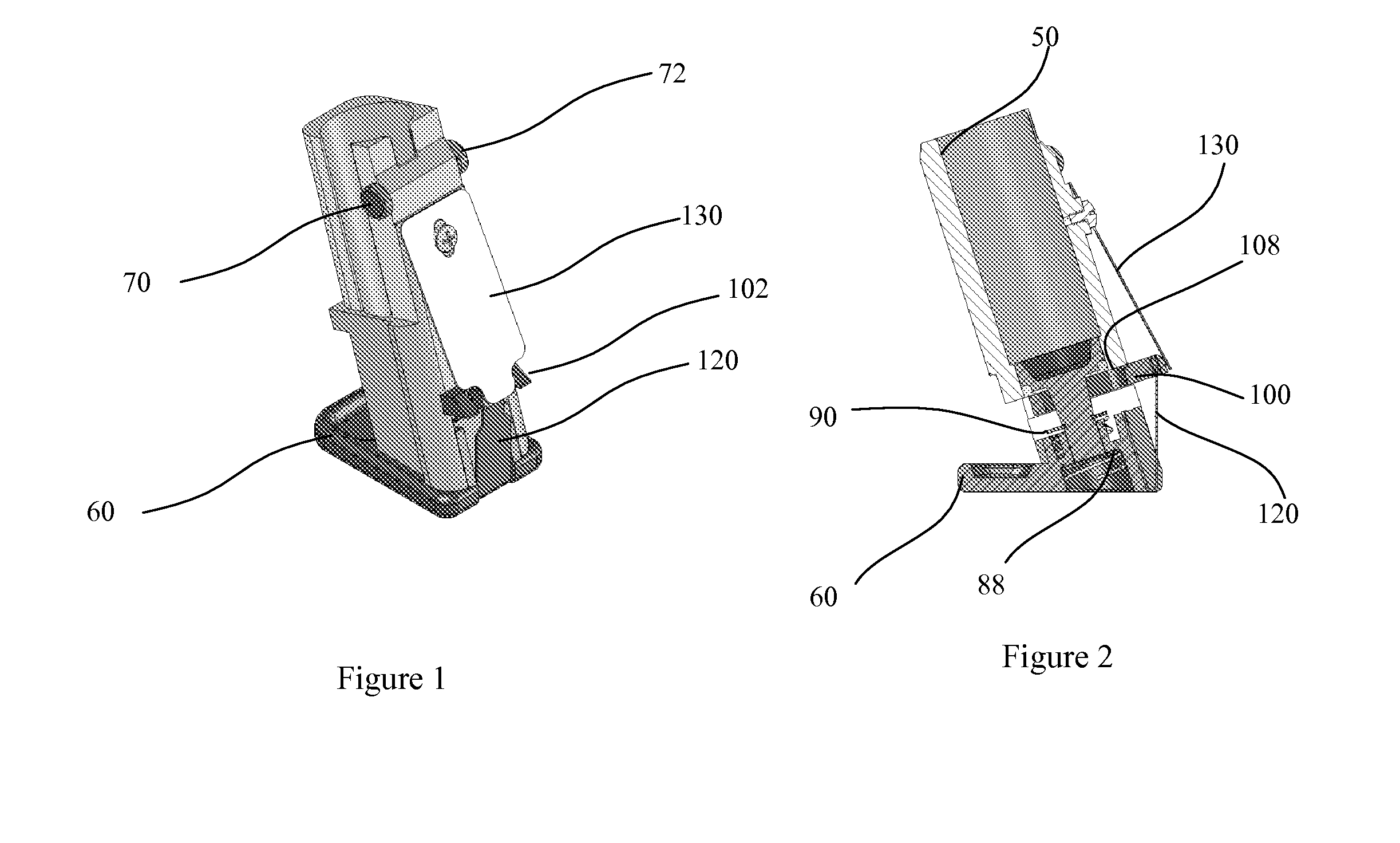
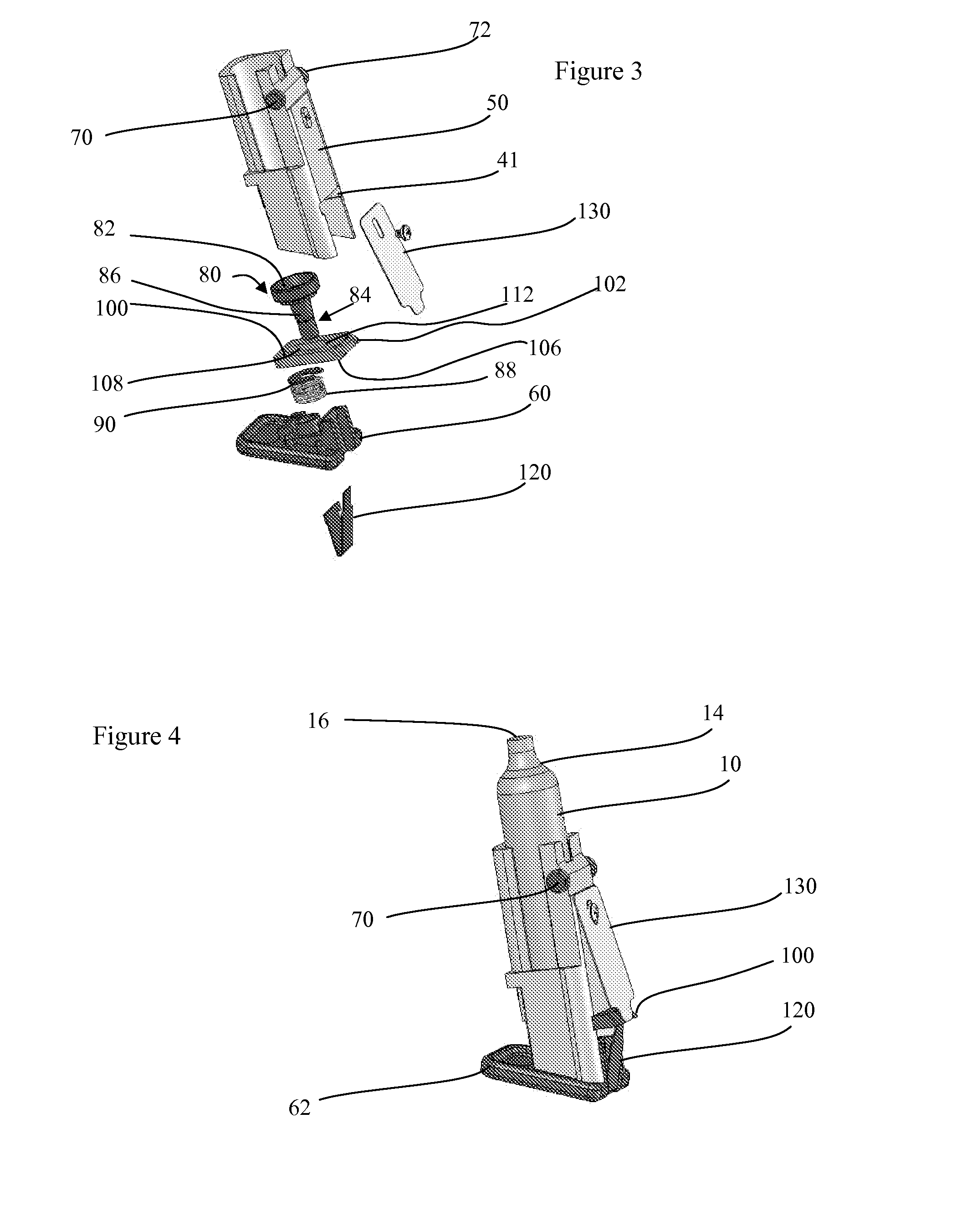
[0014]In one configuration, a magazine assembly is provided for presenting a pressure cartridge to a gas powered gun. The magazine assembly includes a magazine having a pressure cartridge receiving sleeve, wherein a cartridge support is biased with respect to sleeve to urge the pressure cartridge support to a short position. An interlock plate is biased to engage the cartridge support. The bias on the interlock plate is overcome during insertion of the magazine assembly into a magazine chamber of the gun, at which time the cartridge support moves relative to the magazine in response to a seated length of the pressure cartridge. Continued insertion of the magazine assembly allows the bias on the interlock plate to then control the positioning of the interlock plate so as to engage the cartridge support and retain the pressure cartridge relative to the gun. A lever connected to the gun then engages the magazine assembly to translate the magazine assembly relative to the gun and pierce the pressure cartridge.

Problems solved by technology

However, the system of U.S. Pat. No. 4,344,410 does not permit any accommodation for variations in a length of the gas cartridge.
These occurances can reduce the firing capacity of the firearm, as well as lead to damaging of the gas cartridge and / or the firearm.

Method used


Image

  • Magazine Assembly for Presenting a Pressure Cartridge to a Compressed Gas Powered Device
  • Magazine Assembly for Presenting a Pressure Cartridge to a Compressed Gas Powered Device
  • Magazine Assembly for Presenting a Pressure Cartridge to a Compressed Gas Powered Device

Examples


Embodiment Construction

[0026]The present invention provides for the cooperative engagement of a pressure cartridge 10 and a compressed gas powered device, such as a gun 20. It is understood the compressed gas powered device can be any of a variety of devices, including but not limited to sprayers, paintball markers, inflators, guns, tools as well as soda machines. For proposes of description, the present disclosure is set forth in terms of the compressed gas powered device configured as a gun. It is not intended this specific configuration limit the scope of the invention.

[0027]The pressure cartridge 10 is operably retained and aligned with the gun 20 so that pressurized gas from the cartridge is selectively passed through the gun to provide a motive force for the gun.

[0028]The term pressure cartridge 10 is used to encompass any of a variety of sealed pressurized containers retaining a volume of pressurized gas, wherein the seal is selectively punctured to expose the retained pressurized gas to the gun fo...


PUM


Abstract

A magazine assembly presents a pressure cartridge to a compressed gas powered device, such as a gun, wherein the magazine assembly has a cartridge support biased with respect to a magazine to urge the pressure cartridge to a short (or seated) position, wherein an interlock plate is biased to engage the cartridge support. The bias on the interlock plate is overcome during insertion of the magazine assembly into a magazine chamber, at which point the cartridge support moves relative to the magazine in response to a seated length of the pressure cartridge. The bias on the interlock plate then controls the positioning of the interlock plate to engage the cartridge support and retain the pressure cartridge relative to the magazine assembly. A lever connected to the gun then engages the magazine assembly to translate the magazine assembly relative to the gun and pierce the pressure cartridge.

Description

CROSS-REFERENCE TO RELATED APPLICATIONS[0001]Not Applicable.STATEMENT REGARDING FEDERALLY SPONSORED RESEARCH OR DEVELOPMENT[0002]Not Applicable.REFERENCE TO A “SEQUENCE LISTING”[0003]Not Applicable.BACKGROUND OF THE INVENTION[0004]1. Field of The Invention[0005]The present invention relates to the presentation of a pressure cartridge to a compressed gas powered device, and more particularly to the presentation of the pressure cartridge to a hand held compressed gas powered device such as a gun.[0006]2. Description of Related Art[0007]Various guns, such as handguns and rifles employ the selective release of a pressurized gas to launch a projectile. In some constructions, the pressurized gas is air which is compressed by the user, such as by a hand actuated pump. In other configurations, a pressurized container is used to retain a supply of pressurized gas. In these latter configurations, the pressurized container must be fluidly connected to the gun so that the pressurized gas can be...

Claims


Application Information

Patent Timeline
IPC IPC(8): F41B11/00F41B11/62
CPCF41B11/62F41A9/61
Inventor KAMINKER, EDUARDMARTIN, JAMES M.SNYDER, DAVID C.REIFSNYDER, ROBERT
Owner CROSMAN CORP
Learn More