Eureka AIR delivers breakthrough ideas for toughest innovation challenges, trusted by R&D personnel around the world.

Droop stop mechanism for helicopter rotor blade

a technology of rotor blade and stop mechanism, which is applied in the field of aviation, can solve the problems of rotor components being damaged, blades tending to sag more, and more restrictive limits for flapping and drooping, and achieves the effects of easy installation and configuration, small size, and light weigh

Active Publication Date: 2007-08-23
THE BOEING CO
View PDF6 Cites 6 Cited by
  • Summary
  • Abstract
  • Description
  • Claims
  • Application Information

AI Technical Summary

Benefits of technology

[0011] In accordance with the exemplary embodiments thereof described herein, the present invention provides a CF-actuated helicopter blade droop- or flap-stop mechanism that is smaller in size, lighter in weight, easier to install and configure for reliable operation, and whose susceptibility to damage and malfunction due to exposure to the elements is substantially less than the droop stop mechanisms of the prior art.
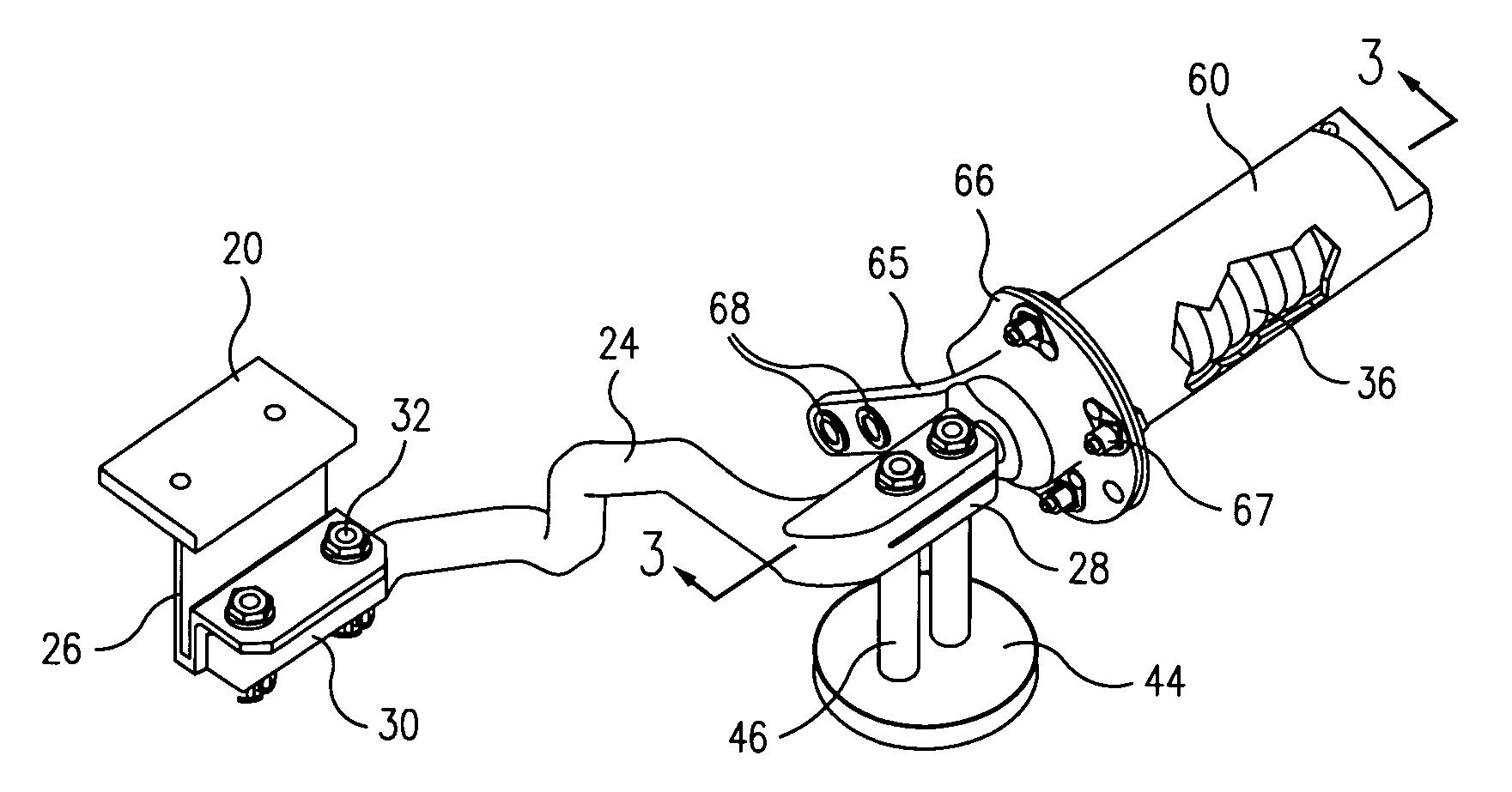
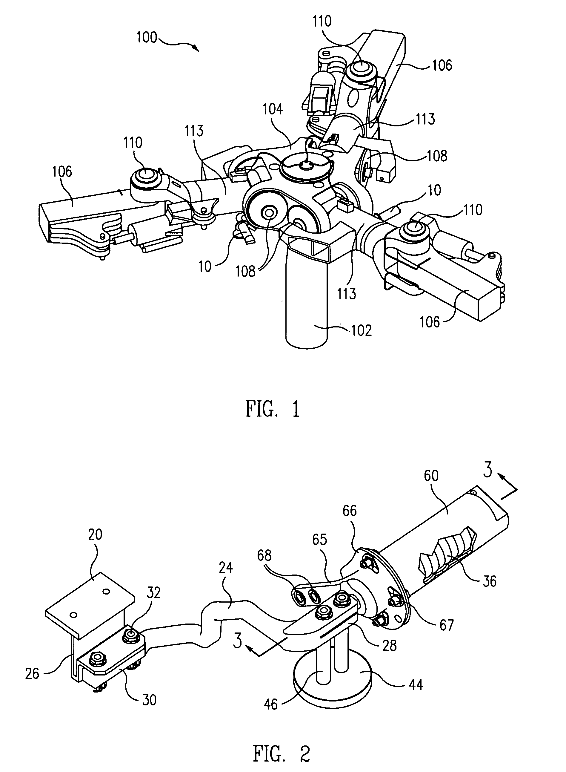
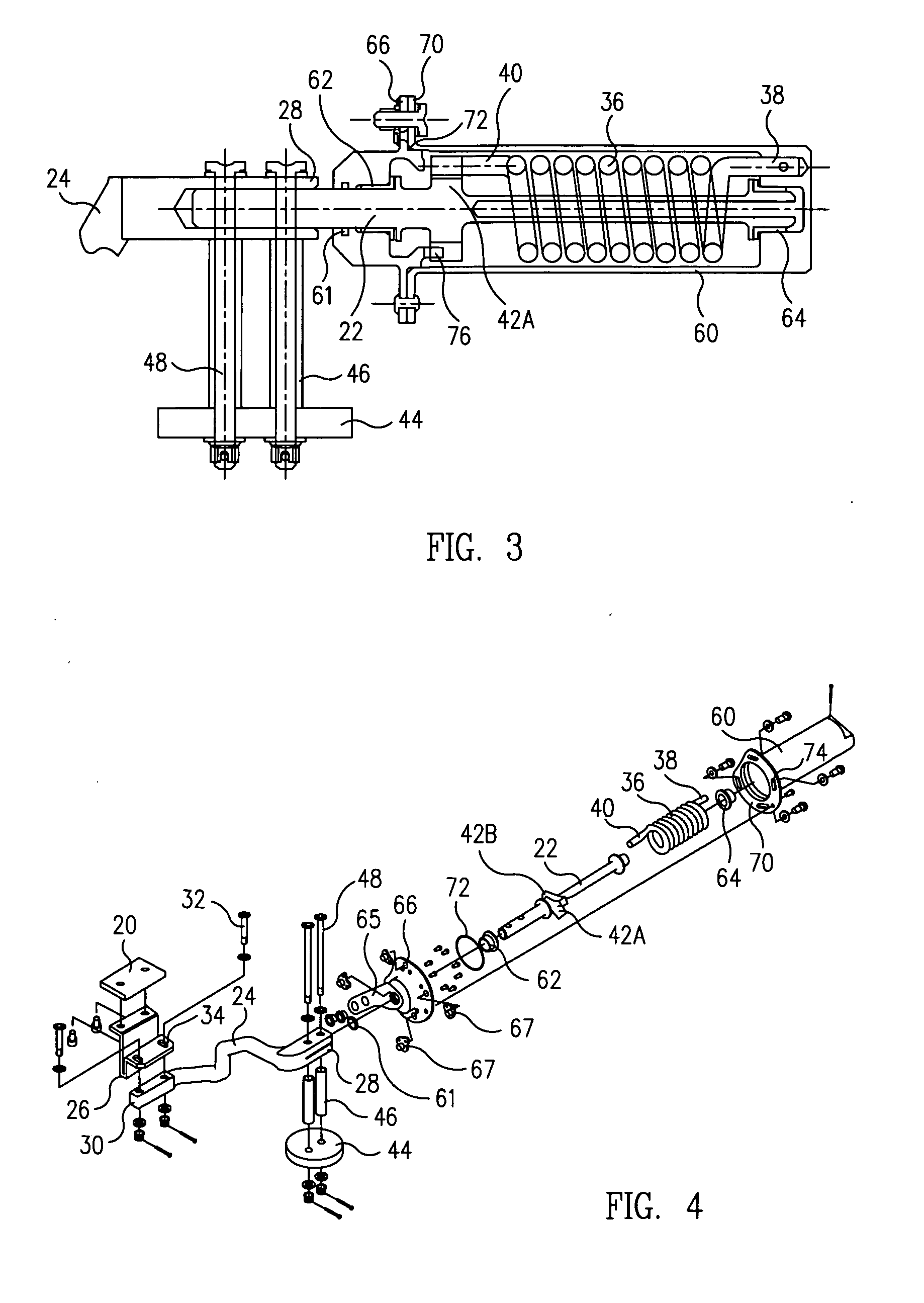
[0013] The shaft is rotatably mounted to the hub of the rotor with its long axis disposed perpendicular to plane of rotation of the interposer. The arm has a first end attached at a right angle to an end of the shaft for conjoint rotation therewith, and an opposite, second end. The interposer is attached to the second end of the arm by the spring support, which has a U-shaped cross section configured to resist tangential movement of the interposer relative to the stops, but to allow some radial movement of the interposer relative thereto. The angular position of the spring support relative to the arm is also adjustable to permit fine adjustment of the interposer's position when it is disposed between the two stops.
[0014] A torsion spring is disposed concentrically about the shaft, and has a first end that is fixed, and an opposite second end coupled to the shaft so as to bias the shaft, arm, spring support, and hence, the interposer, to a first angular position disposed between the two stops such that downward rotational deflection of the blade about the flap hinge, or droop, is substantially limited. A weight is disposed on the arm and shaft at the end of an elongated spacer such that, with rotation of the rotor, centrifugal force acting on the spinning weight causes the shaft and arm to rotate conjointly, and at the appropriate rotational speed, to overcome the bias of the torsion spring and urge the interposer out from between the stops and to a second angular position that allows a greater droop of the blade.
[0017] In a preferred exemplary embodiment, the torsion spring and all but a first end portion of the shaft are enclosed in a sealed housing, or canister, to reduce their susceptibility to damage and malfunction due to exposure to the elements, such as icing conditions. The shaft is rotatably journalled in sealed bushings for rotation within the canister. The canister is fixed to the hub, and the initial angular position of the shaft relative to the canister is adjustable such that the shaft applies a selected amount of torsional bias, or torque, to the interposer through the shaft. The canister prevents ice from forming on the spring and shaft and adversely affecting the operation of the mechanism.

Problems solved by technology

Flap stops are required to prevent the rotor blade from “sailing” up uncontrollably, and thereby damaging rotor components.
However, when the blade is not rotating, and the additional stiffening imparted to it by centrifugal force therefore absent, the blade tends both to sag more, due to the effect of gravity, and to sail more, e.g., as a result of wind gusts acting on it.
Therefore, to prevent rotor damage, the flapping and drooping limits are more restrictive when the blade is either not rotating or rotating slowly.
Thus, if the re-insertion does not occur at the correct rpm, component damage and / or aircraft performance problems can result.
Folding operations are highly susceptible to interference caused by wind gusts, and typically require that all flapping motion to be locked-out during the folding sequence.
However, the prior art mechanism has a number of disadvantages associated with it, including its relatively large size and weight, complexity of installation and configuration for correct operation, and its susceptibility to damage due to the exposure of its components to the elements, e.g., icing conditions, thereby risking mechanical failure and damage to the aircraft caused by mechanical interference between the components of the mechanism.
However, the relative size and complexity of the prior art design now being used prohibits its use as a flap stop on the CH-47 Chinook and other helicopters.
Accordingly, there is a long felt but as yet unsatisfied need in the rotorcraft field for a CF-actuated helicopter blade flap- or droop-stop mechanism that is substantially smaller in size, lighter in weight, easier to install and configure for reliable operation, and whose susceptibility to damage and malfunction due to exposure to the elements is substantially less than that of current designs.

Method used


Image

  • Droop stop mechanism for helicopter rotor blade
  • Droop stop mechanism for helicopter rotor blade
  • Droop stop mechanism for helicopter rotor blade

Examples


Embodiment Construction

[0029]FIG. 1 is a partial top and side perspective view of a main rotor 100 of a helicopter incorporating a rotor shaft 102, a hub 104 disposed at the end of the shaft, and three blades 106 radiating outward from it, each of which is equipped with an exemplary embodiment of a CF-actuated droop stop mechanism 10 in accordance with the present invention. As illustrated in FIG. 1, each of the rotor blades is pinioned to the hub by a pair of hinges, viz., a “flap hinge”108 and a “lag hinge”110 that respectively enable the associated blade to pivot up and down, and fore and aft, relative to the hub. Additionally, the blade and lag hinge are rotatably coupled to the flap hinge by a pitch shaft 112 (see FIG. 6) rotatably contained within a pitch shaft housing 113 for conjoint rotation with the blade about the long axes thereof.

[0030] As respectively illustrated in the enlarged perspective views of the hub 104 and the pitch shaft 112 of FIGS. 5 and 6, the exemplary droop stop mechanism 10 ...


PUM


Abstract

A droop stop mechanism for a helicopter rotor blade includes a pair of opposing stops disposed on opposite sides of the blade's flap hinge. An interposer is mounted at the end of an arm on a rotatable shaft for rotation in a plane perpendicular to the hinge. A torsion spring disposed concentrically about the shaft has a first end that is fixed and a second end coupled to the shaft to bias the interposer to a position disposed between the stops, thereby limiting blade droop. A weight is attached to the shaft such that, with rotation of the rotor, centrifugal forces acting on the weight cause the shaft and arm to rotate so as to overcome the bias of the spring and urge the interposer out from between the stops, thereby allowing greater blade droop. The spring and shaft are sealed in a canister for protection from the elements.

Description

STATEMENT REGARDING FEDERALLY SPONSORED RESEARCH OR DEVELOPMENT [0001] This invention was made with Government support under contract DAAH01-99-3-R001 awarded by the U.S. Army. The Government has certain rights in this invention.TECHNICAL FIELD [0002] This invention pertains to the field of aviation, in general, and more particularly, to a mechanism that uses a torsional spring and centrifugal force to limit the amount of flap or droop experienced by the main rotor blades of a helicopter. BACKGROUND [0003] Helicopter rotor systems typically employ stops to limit the amount of vertical deflection experienced by the outer portions of the rotor blades relative to the flap hinge of the blade. These may include stops for limiting both downward, or “drooping,” deflection, and upward, or “flap-ping” deflection. Stops for limiting downward deflections are called “droop stops,” and stops for limiting upward deflection are called “flap stops.” Droop stops are required to prevent the rotor bla...

Claims


Application Information

Patent Timeline
IPC IPC(8): B64C11/28
CPCB64C27/322
Inventor CARBAUGH, STEVEN R.SPEAR, STEVEN J.
Owner THE BOEING CO
Why Eureka
Eureka Blog
Learn More