Image forming apparatus

a technology of image forming apparatus and forming tube, which is applied in the direction of electrographic process apparatus, instruments, optics, etc., can solve the problems of carrier splashing, difficult to obtain enough resolution, and inability to maintain the line width only by controlling the background voltag

Inactive Publication Date: 2008-07-17
KONICA MINOLTA BUSINESS TECH INC
View PDF3 Cites 13 Cited by
  • Summary
  • Abstract
  • Description
  • Claims
  • Application Information

AI Technical Summary

Benefits of technology

[0012]It is therefore an object of the present invention is to provide an image forming apparatus, which is capable of maintaining the predetermined line width within a range where the fogged / blurred image and carrier splash do not occur, even if two-component developer is used

Problems solved by technology

However, in the image writing device adopting a two-component developer and LPH (LED Print Head), the line width cannot be maintained only by controlling the background voltage.
Thus, carrier splashing tends to occur.
Further, particularly in the high-speed machine, it is difficult to obtain enough resolution by utilizing the method of controlling the emitting time of LPH.

Method used


Image

  • Image forming apparatus
  • Image forming apparatus
  • Image forming apparatus

Examples


Embodiment Construction

[0024]An image forming apparatus of the present invention will be explained based on FIG. 1 hereinafter.

[0025]In an explanation of an embodiment in the present invention, a scope of technology of the present invention is not limited to the terms used in this specification.

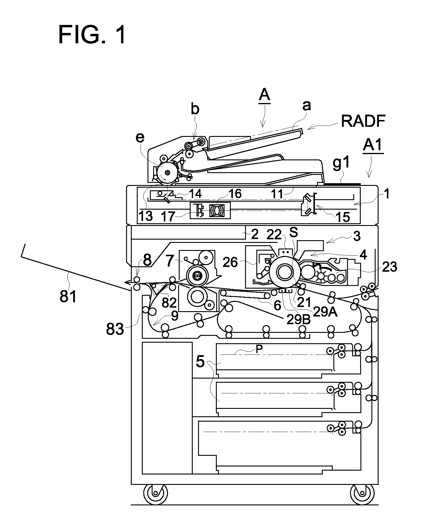
[0026]FIG. 1 illustrates a schematic diagram of an example of an image forming apparatus of the embodiment.

[0027]In FIG. 1, an image forming apparatus A, which is an image forming apparatus of the present invention, includes a reversing automatic document feeder RADF and an apparatus main body A1.

[0028]The reversing automatic document feeder RADF disposed on the top of the apparatus main body A1 is capable of opening and closing. An original document on a document feed tray “a” is conveyed to a feed roller “b” and a conveyance drum “e” then the original document is conveyed.

[0029]The apparatus main body A1 includes an image reading device 1, an image processing section 2 (may be named a controlling section, hereina...


PUM


Abstract

An image forming apparatus includes: a photoreceptor, a charging unit which charges the photoreceptor; an exposing unit which forms a latent image onto the photoreceptor; a developing unit which develops the latent image to a toner image; a sensor which detects a line width of a toner patch formed on the photoreceptor by the exposing unit and the developing unit; and a controller which changes a background voltage based on the line width detected by the sensor during an image forming operation so that the line width is secured within a predetermined line width. The controller returns the background voltage to value adjacent to an initial setting background voltage and changes the light amount of the exposing unit by a light amount corresponding to a returning amount of the background voltage.

Description

[0001]This application is based on Japanese Patent Application No. 2007-003183 filed on Jan. 11, 2007, which is incorporated hereinto by referenceBACKGROUND OF THE INVENTION[0002]The present invention relates to an image forming apparatus of an electro-photographic system for developing a latent image on a photoreceptor with developer to form a toner image.[0003]In an image forming process of the electro-photographic system, the image density and the line width of an image formed change according to the temperature and humidity of the setting location of the image forming apparatus, the photoreceptor (an image carrier) and a usage time of the developer.[0004]In order to stabilize the image quality of a print image, the image quality and the line width have to be stabilized. With respect to the technologies for stabilizing the line width, there have been provided a method for controlling a background voltage (fogging / blurring voltage: This voltage is defined as the difference between...

Claims


Application Information

Patent Timeline
Patent Type & Authority Applications(United States)
IPC IPC(8): G03G15/00G03G15/043G03G15/06
CPCG03G15/326G03G15/043G03G15/5041G03G2215/00042
Inventor YAMAGUCHI, TORUKOSHIMURA, YASUSHI
Owner KONICA MINOLTA BUSINESS TECH INC
Why Eureka
Try Eureka