Swivel single pole electrical connectors

a single-pole, electrical connector technology, applied in the direction of electrically conductive connections, coupling device connections, electrical apparatus, etc., can solve the problems of reducing the strength of the electrical connector, the rotational stress of the locking mechanism, and the damage of the rotational force and stress on the electrical connector components, so as to reduce the amount of force applied and reduce the effect of stress

Inactive Publication Date: 2008-07-17
VAN SYST E R L
View PDF5 Cites 19 Cited by
  • Summary
  • Abstract
  • Description
  • Claims
  • Application Information

AI Technical Summary

Benefits of technology

[0022]Another advantage of the present invention can be to provide new swivel single pole electrical connectors.
[0023]Another advantage of the present invention can be to provide single pole electrical connectors that allow relative rotation between a connector body and an electrical contact.
[0024]A further advantage of the present invention can be to connect an electrical connector having an electrical cable to a mating electrical connector without twisting the electrical cable.
[0025]Yet another advantage of the present invention can be to reduce the amount of force applied by an operator to couple and / or uncouple electrical connectors.
[0026]Further advantages of the present invention can be to reduce or eliminate stress applied to electrical connectors during coupling with a mating electrical connector, when coupled to the mating electrical connector, and / or during uncoupling from the mating electrical connector.
[0027]Another advantage of the present invention can be to reduce or prevent inadvertent opening of two electrical connectors connected together.

Problems solved by technology

For example, the locking mechanism, which locks the two electrical connectors together, is subject to rotational stress due to the twisted cable.
The rotational forces and stresses can be detrimental to the electrical connector components.

Method used


Image

  • Swivel single pole electrical connectors
  • Swivel single pole electrical connectors
  • Swivel single pole electrical connectors

Examples


Embodiment Construction

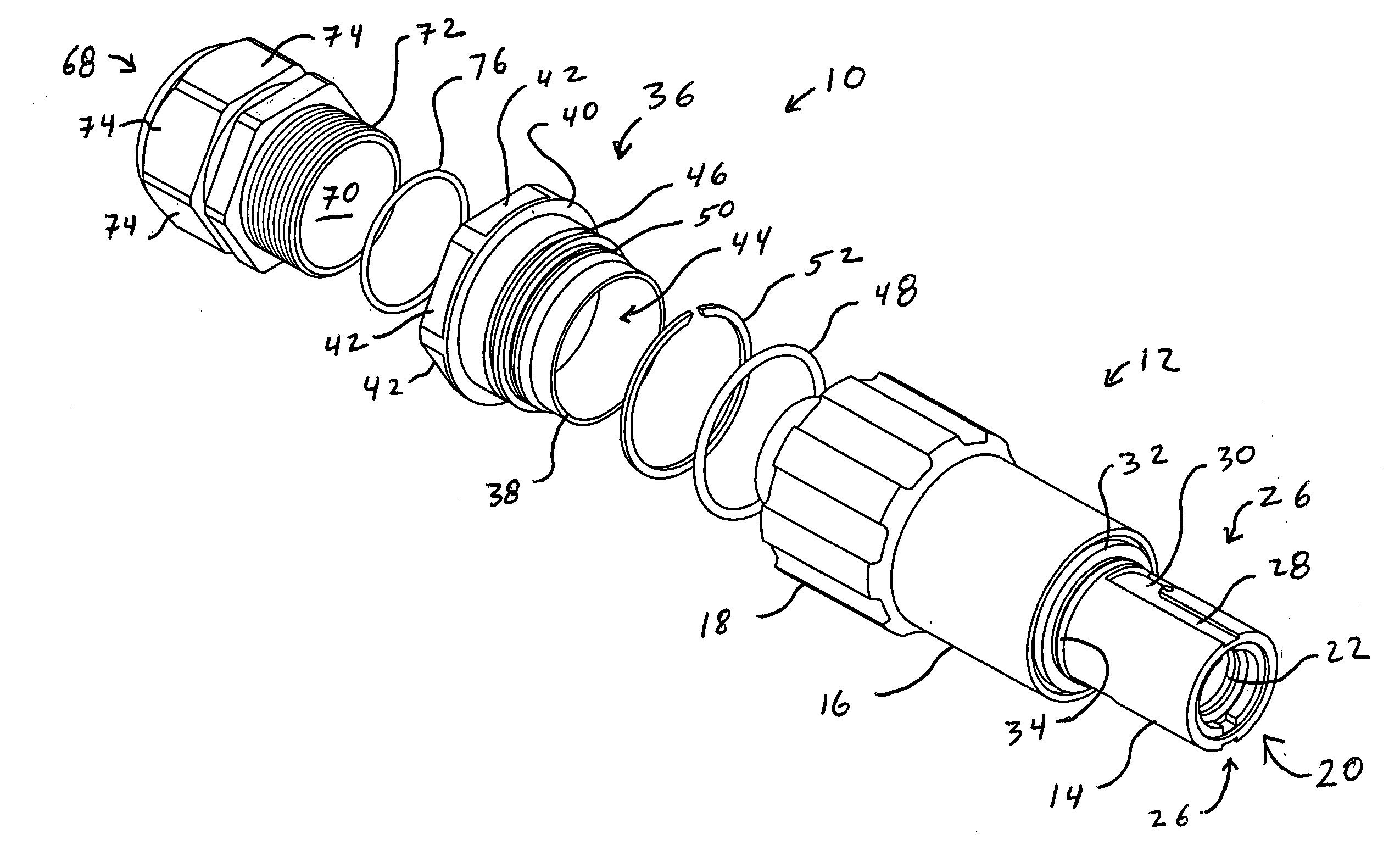
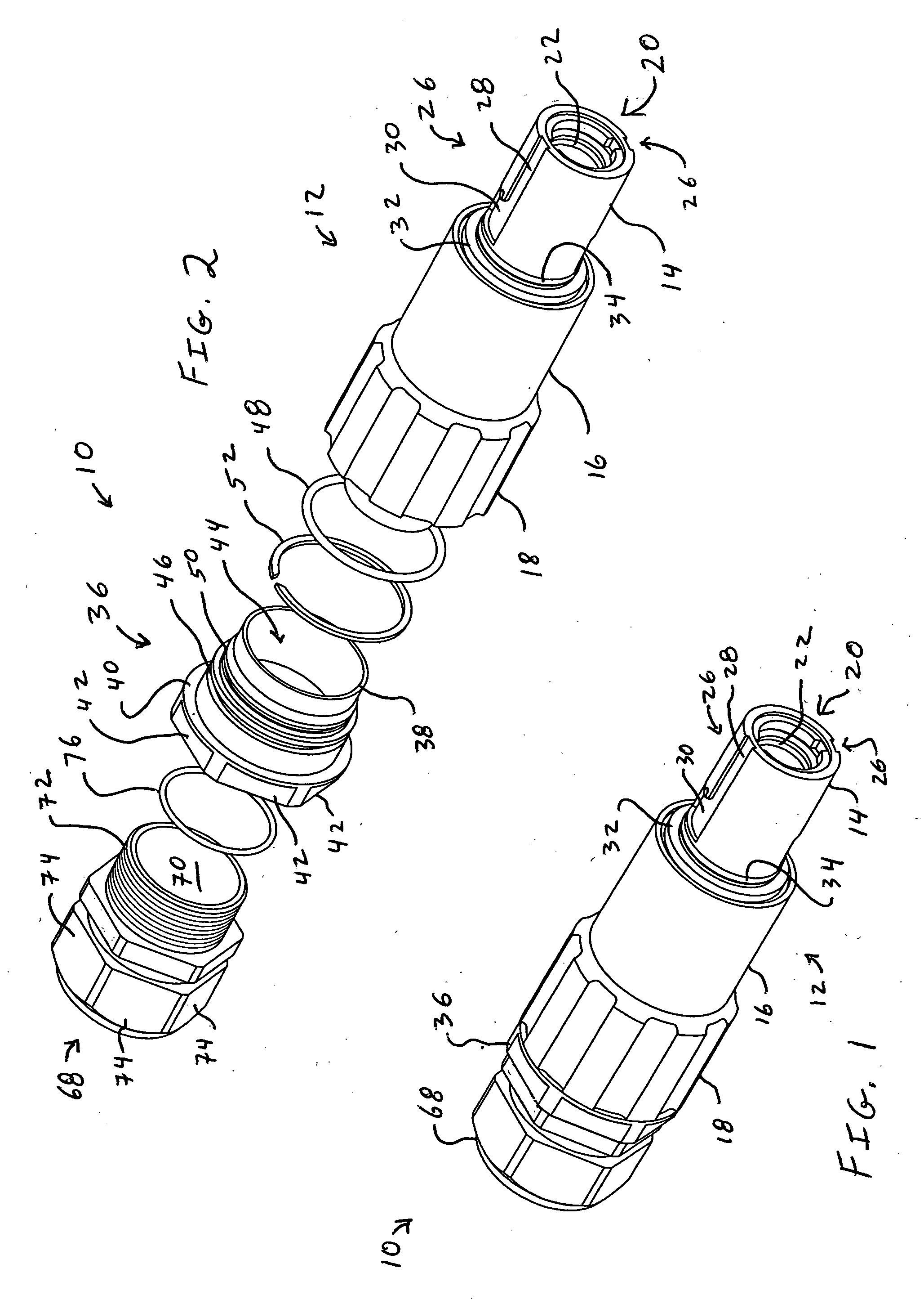
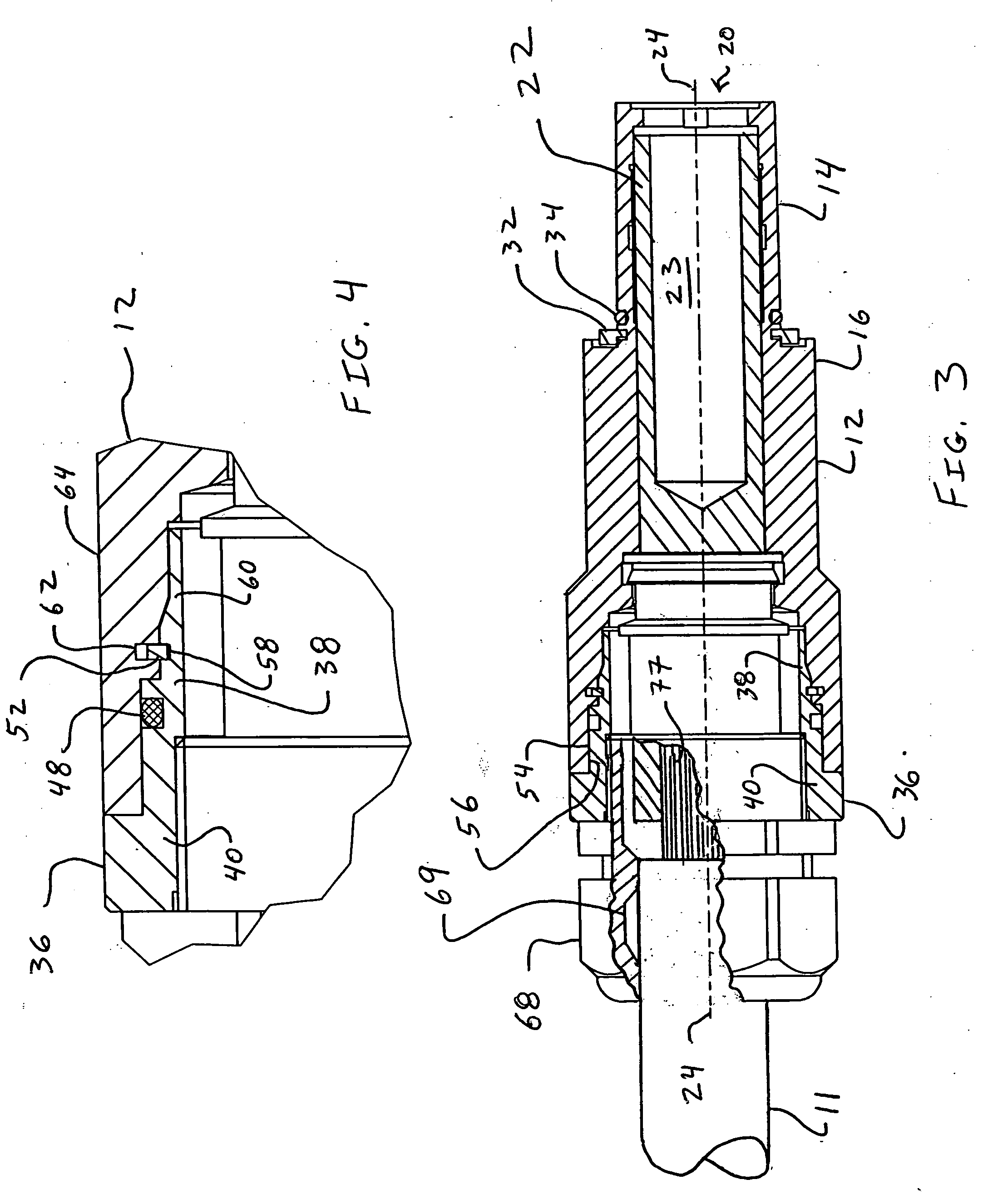
[0041]One example of a swivel single pole electrical connector 10 according to the present invention is shown in FIGS. 1-4. The swivel single pole electrical connector 10 is attached to a free end of an electrical cable 11 (FIG. 3) and can be connected to and disconnected from a mating electrical connector (not shown). The embodiment of the present invention shown in Figure is a single pole receptacle electrical connector which can be engaged with a mating single pole plug electrical connector. Existing single pole electrical connectors, including plugs and receptacles, are available from Van-System s.r.l., Milan, Italy and Clements National Company, Chicago, Ill. The present invention is an improvement over existing electrical connectors, particularly single pole electrical connectors. The swivel single pole electrical connector 10 allows for axial rotation of a body portion of the electrical connector that engages with the mating electrical connector without axial rotation of the ...


PUM

PropertyMeasurementUnit
cylindrical shapesaaaaaaaaaa
diameteraaaaaaaaaa
rotational forceaaaaaaaaaa

Abstract

An electrical connector, particularly a single pole electrical connector, has a first connector body portion having an engagement structure capable of engagement with a mating electrical connector. An electrical contact is provided adjacent the first connector body portion. A second connector body portion is connected to the electrical contact and has an electrical cable engagement portion capable of engagement with an electrical cable. The first and second connector body portions are rotatably engaged with each other and rotatable relative to each other about a longitudinal axis of the electrical connector. The first connector body portion rotates about the longitudinal axis independently of the second connector body portion and the electrical contact. Rotation of the electrical cable is not required to connect the single pole electrical connector to the mating electrical connector.

Description

BACKGROUND OF THE INVENTION[0001]The present invention generally pertains to electrical connectors or electrical interconnecting devices. More specifically, the present invention pertains to single pole electrical connectors having an electrical contact and a connector body for connecting to a mating electrical connector in which the connector body and the electrical contact can rotate relative to each other, i.e. swivel. In embodiments of the present invention, electrical connectors provide for rotation of the connector body during coupling to the mating electrical connector without rotation of an electrical cable electrically connected to the electrical contact. The present invention also pertains to methods related to the electrical connectors, such as methods of making electrical connectors and methods of using electrical connectors.[0002]Single pole electrical connectors exist. Single pole electrical connectors typically have a housing and an electrical contact which are rigidl...

Claims


Application Information

Patent Timeline
Patent Type & Authority Applications(United States)
IPC IPC(8): H01R3/00H01R43/027
CPCH01R13/502H01R13/5202Y10T29/49218H01R13/623H01R13/625H01R13/622
Inventor VANZO, AUGUSTO
Owner VAN SYST E R L
Why Eureka
Try Eureka