
Surgical support for patient limb

a technology for supporting devices and patients, applied in the field of surgical support for patients' limbs, can solve the problems of increasing surgery costs, no effective support device has been proposed as a rest for the patient's limb, i.e., arm or leg, etc., and achieves the effect of effective suppor

Active Publication Date: 2008-07-24
WALCZYK STEPHEN L
View PDF15 Cites 52 Cited by
  • Summary
  • Abstract
  • Description
  • Claims
  • Application Information

AI Technical Summary

Benefits of technology

[0005]Accordingly, it is an object of the invention to provide an effective support for a patient's arm or leg during a surgical operation and which avoids the drawbacks of the prior art.
[0006]It is another object to provide a patient arm rest or leg rest for surgical use, which is sturdy and convenient to use.
[0008]It is a still further object to provide a patient arm rest or leg rest that can be oriented into a wide range of heights and angles to suit the need to orient any patient limb in any given position.
[0012]The tray and all the support portions may be fabricated from a surgical grade of stainless steel, so the entire device can be easily cleaned and sanitized.

Problems solved by technology

If the arm position changes during surgery, it can make the procedure more complex.
However, to date no effective support device has been proposed as a rest for the patient's limb, i.e., arm or leg, while undergoing surgery or other medical procedure.
However, that device is only intended as a cushioning stabilizer for a patient that is oriented into a prone position.
Also, because the Cloward device is made of foam plastic, it is difficult or impossible to render sterile after a procedure, and thus has to be discarded, thereby elevating the costs of surgery.
There are other procedures as well where the patient's leg needs to be elevated at a particular height and a particular angle, but there is no convenient means now available to hold the patient's lower limb comfortably and stably.

Method used


Image

  • Surgical support for patient limb
  • Surgical support for patient limb
  • Surgical support for patient limb

Examples


Embodiment Construction

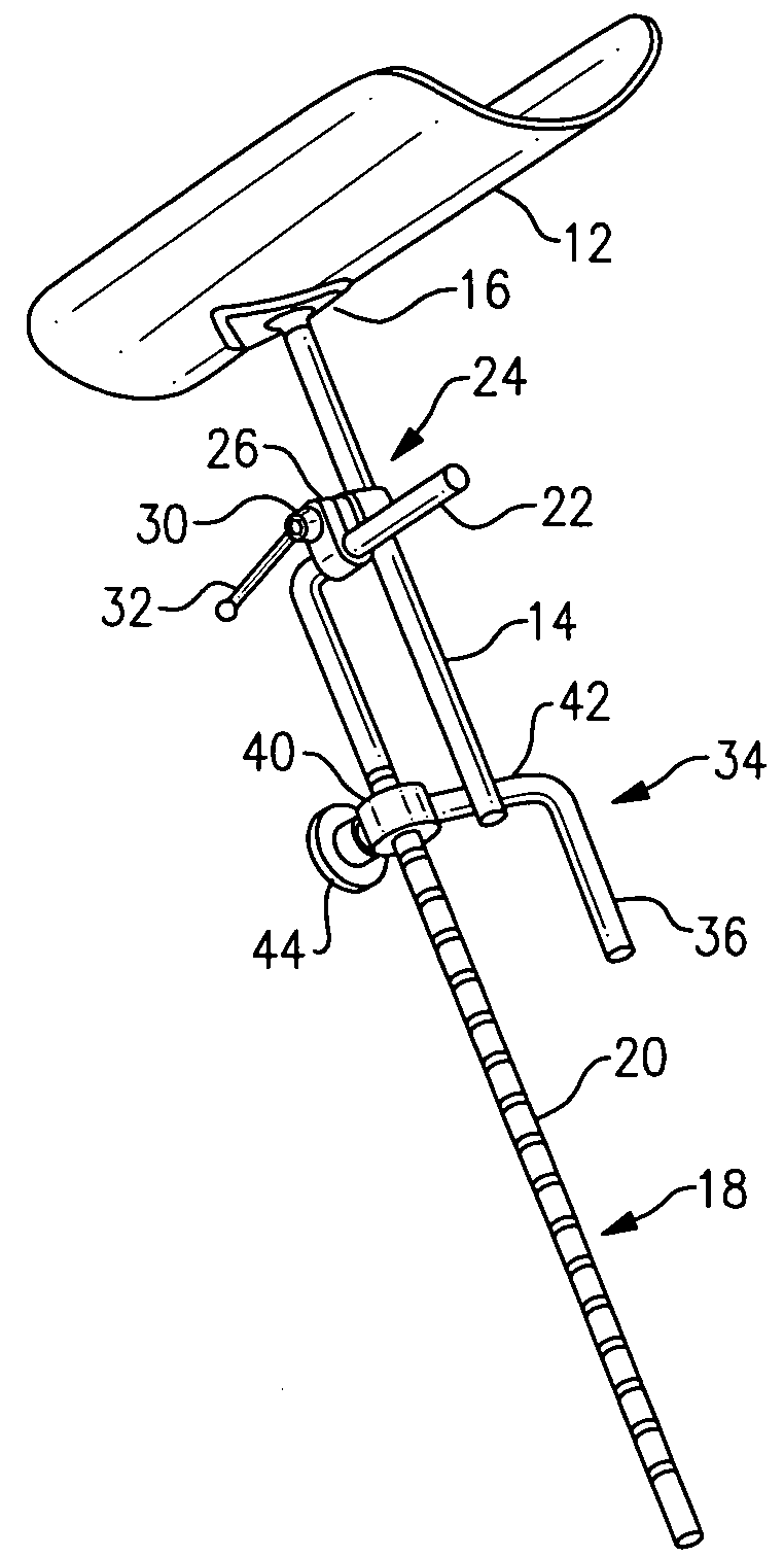
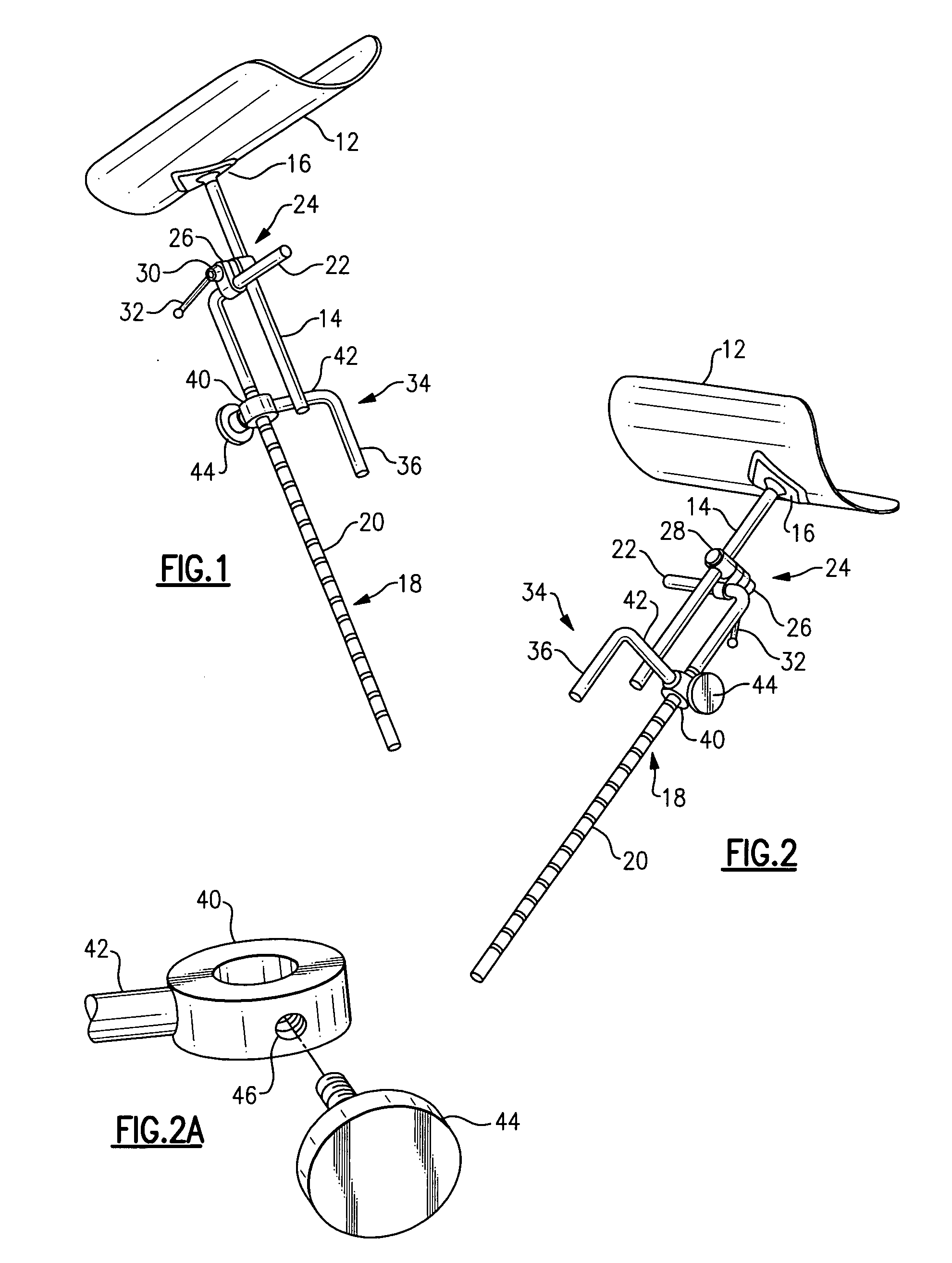
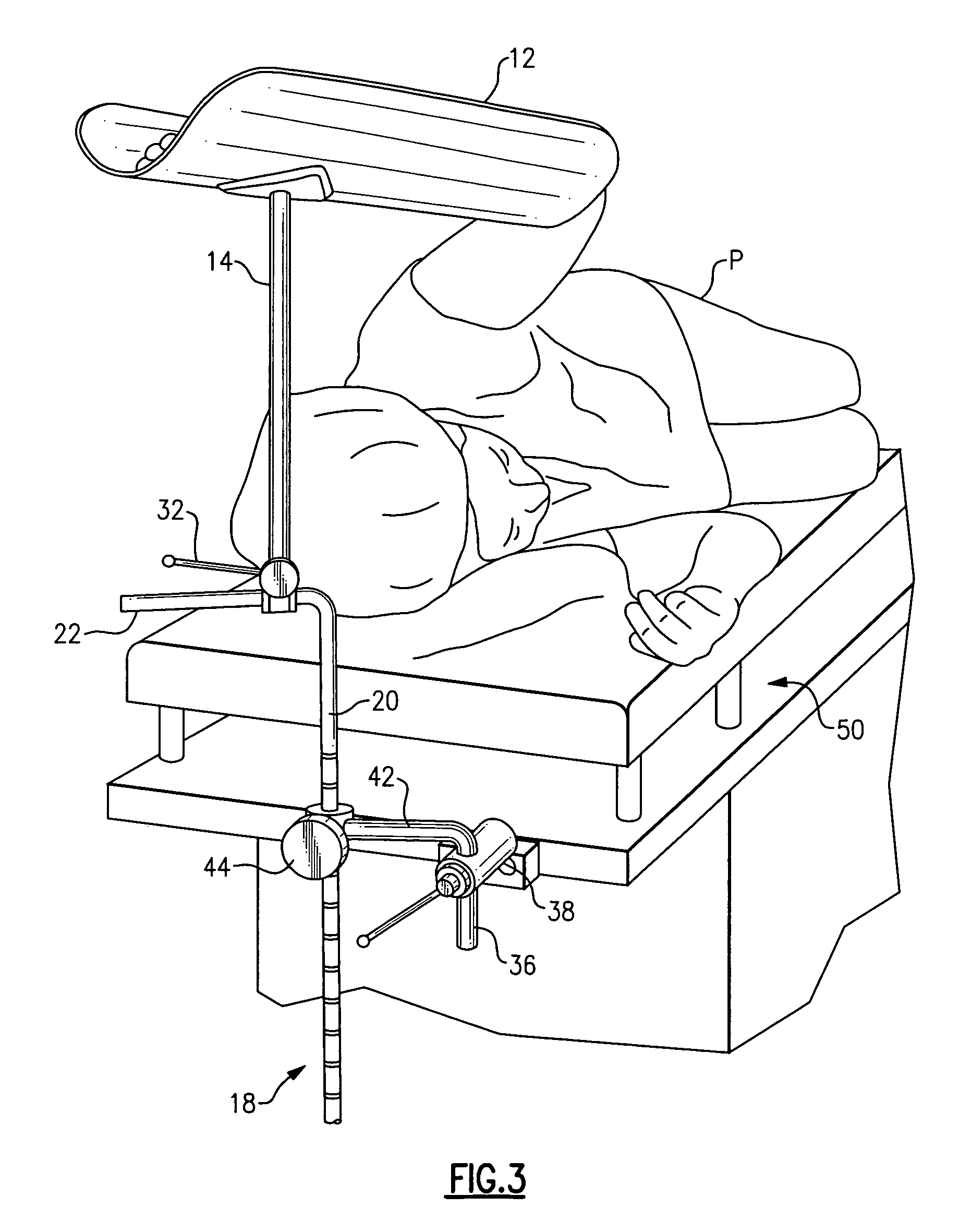
[0019]With reference to the Drawing, and initially to FIGS. 1 and 2, a surgical arm rest assembly 10 has a stainless steel tray 12, here in the form of a portion of a cylinder, being arcuate in the cross-ways direction and generally straight in the lengthwise direction, as shown. The tray 12 can be about sixteen to twenty inches in length, to correspond generally to the size of a patient's forearm. A post or rod 14 extends downward from the underside of the tray 12, and a diamond-shaped brace 16 secures the rod to the under surface of the tray 12. A long arm 18, which is in the form of a generally L-shaped rod or post of circular cross section, has a vertical arm portion 20 that is elongated in the vertical direction and extends for twenty-four to thirty inches. The long arm 18 has a cross arm portion 22 at its upper end that extends at a right angle, i.e., horizontally, for about six inches. A clamp member 24 is secured at an upper end of the long arm 18 and in this embodiment the ...


PUM


Abstract

A surgical arm rest or leg rest for supporting a patient's limb has concave tray or trough supported on a post member that extends downward. An elongated rod member situated below the tray with clamp member adjustably supports the post of the tray. A clamp member permits the rotation angle and tilt angle of the support post to be adjusted. An L-shaped support arm has a vertical arm portion adapted to be received into a support clamp mounted on the surgical table, and a horizontal arm that holds a sleeve member which supports the rod member. A locking lever on the sleeve member locks the rod member in place in the sleeve member.

Description

BACKGROUND OF THE INVENTION[0001]This invention relates to medical and surgical devices, and is more particularly concerned with devices and apparatus for stabilizing and supporting a patient's arm or leg during a surgical procedure or other medical procedure.[0002]In some surgical procedures, in particular those which may involve the side of the thorax or rib cage, it is necessary for the patient to hold his or her arm in an elevated position. If the arm position changes during surgery, it can make the procedure more complex. However, to date no effective support device has been proposed as a rest for the patient's limb, i.e., arm or leg, while undergoing surgery or other medical procedure.[0003]A foam cushion type arm rest exists, as discussed in U.S. Pat. No. 4,730,801 to Cloward. However, that device is only intended as a cushioning stabilizer for a patient that is oriented into a prone position. The patient's arms are not elevated above the head, and thus the Cloward arm rest i...

Claims


Application Information

Patent Timeline
Patent Type & Authority Applications(United States)
IPC IPC(8): A61G13/12A61B19/00
CPCA61G13/101A61G13/12A61G2200/325A61G13/1245A61G2200/322A61G13/1235
Inventor WALCZYK, STEPHEN L.
Owner WALCZYK STEPHEN L
Learn More