Drum rim gap or space dimension gauge

a technology of space dimension and hoop, which is applied in the direction of mechanical clearance measurement, measurement devices, instruments, etc., can solve the problems of not providing a measurement mechanism to determine the gap between the hoop and the shell lug casing

Inactive Publication Date: 2008-07-24
RANDALL MAY INT
View PDF37 Cites 14 Cited by
  • Summary
  • Abstract
  • Description
  • Claims
  • Application Information

AI Technical Summary

Benefits of technology

[0011]It is an object of the drum gap or space gauge to provide a gauge that is expandable between the hoops of a drum to indicate the length of the tension rods on a drum. The length of the tension rods provides information on the relative tone of a drum head. In an ideal setting the length of the tension rods would all be consistent, thus allowing the sound from the drum head to be in tune with itself.

Problems solved by technology

While this patent also provides a method of evenly pulling the drum skin down the sides of the drum shell to ensure that the drum head is evenly tensioned, it does not provide for a measurement mechanism to determine the gap between the hoop and the shell.
This patent also provides a method of evenly pulling the drum skin down the sides of the drum shell to ensure that the drum head is evenly tensioned, but it does not provide for a measurement mechanism to determine the gap between the hoop and the lug casing of the shell.

Method used


Image

  • Drum rim gap or space dimension gauge
  • Drum rim gap or space dimension gauge
  • Drum rim gap or space dimension gauge

Examples


Embodiment Construction

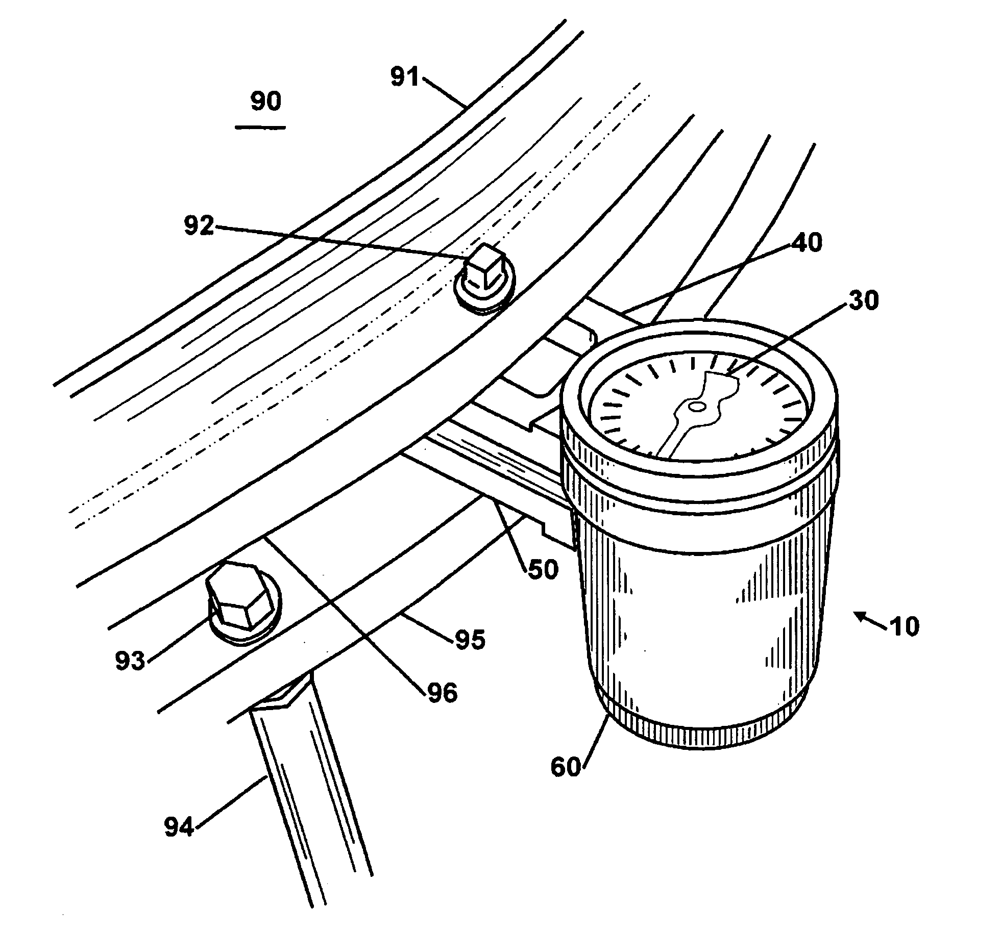
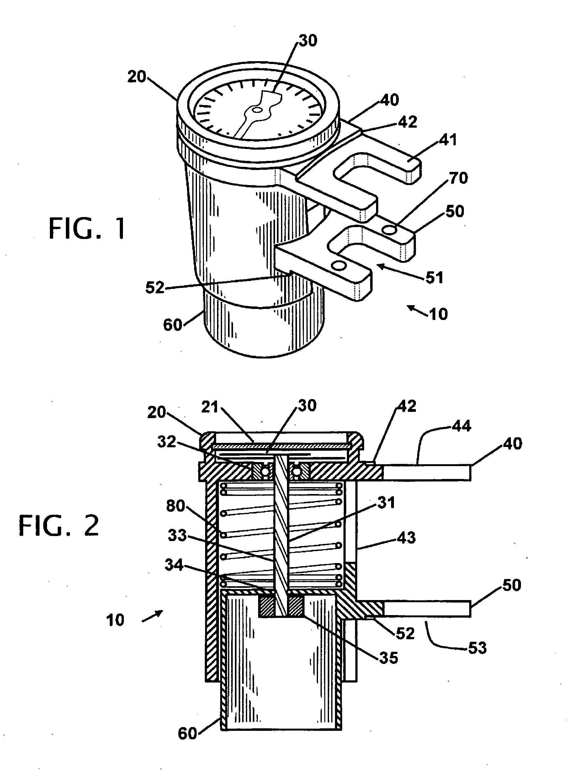
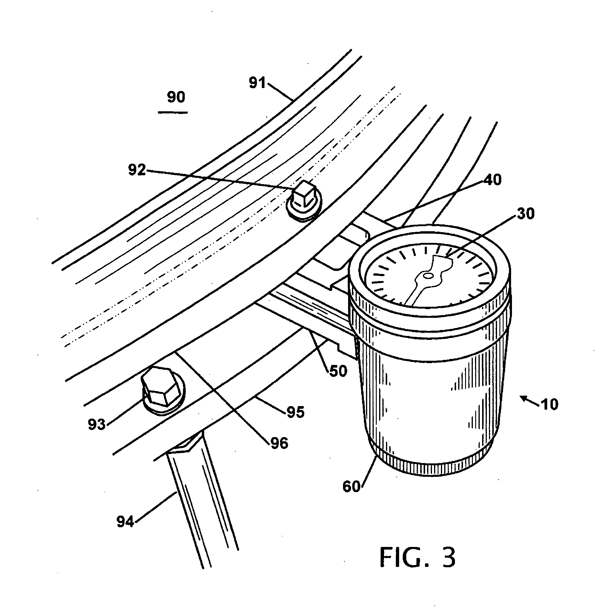
[0024]FIG. 1 shows an isometric view of the drum rim gap or space gauge 10. In a general description of the gauge, the two sets of arms are squeezed together and the gauge is places between two surfaces for measurement. The gauge is released where it expands to measure the distance between the two areas. When the gauge is used to determine the drum head and the hoop distance on a drum, the actual numerical dimension is not as important, but the relative measurement all around the drum should be consistent to ensure the drum head is being evenly tensioned.

[0025]The gauge 10 has a dial with an indicating needle 30 to point to the markings on the faceplate. The indicating needle 30 is preferably covered with a sight glass or similar protective cover. The glass is held in position with a bezel 20. In one contemplated embodiment the bezel has one or more indicator markings and can be turned on the body of the gauge to indicate one or more preferred needle position(s). An upper appendage ...


PUM


Abstract

A drum gauge is disclosed that provides a measurement of the length of the tension rods. In operation the gauge is compressed, placed around each tension rod and released. A display on the gauge provides a numerical value for the relative exposed length of the tension rod(s). The gauge is then moved to each tension rod to determine the length of each rod or the gap or space between the hoops or between the hoop and the lug casings. A nut on the end of each tension rod is adjusted until all the tension rods are adjusted to the same length. The gauge allows the head to be evenly adjusted so the same pitch exists in all locations on the drum head. The gauge has a lip to ensure it is placed consistently on each tension rod and further includes posts to allow the gauge to be used with drums made with different tension rods, counter hoops, claws and lug casings.

Description

CROSS REFERENCE TO RELATED APPLICATION[0001]This application claims the benefit of Provisional 60 / 885,436 filed Jan. 18, 2007 the entire contents of which is hereby expressly incorporated by reference herein.DESCRIPTION[0002]1. Field of the Invention[0003]This invention relates to a drum rim adjustment gauge. More particularly, the present gauge is placed between the drum head hoop and the counter hoop and flange to indicate the length of the tension rods and or gap dimension.[0004]2. Background of the Invention[0005]All drums at one time or another require replacement of the drum head(s) or adjustment of the drum head. The adjustment is usually performed by loosening the tension rods and tightening the rods evenly in a pattern until the drum has the desired tone. Once the desired tone is achieved the drum head area near each tension rod is tapped and each tension rod is individually adjusted so the tone is the same. While this method is the typical method that is used it required a...

Claims


Application Information

Patent Timeline
Patent Type & Authority Applications(United States)
IPC IPC(8): G10D13/02G01B5/14G10D13/16
CPCG01B5/14G10D13/023G10D13/00G10D13/16G10D13/02
Inventor MAY, RANDALL L.
Owner RANDALL MAY INT
Why Eureka
Try Eureka