Respiration monitoring

a technology of respiration monitoring and monitoring surface, applied in the field of respiration monitoring, can solve the problems of artefacts or degradation of 3d representation, near the lungs, and the movement of surrounding tissue, and achieve the effects of less discomfort for patients, rigid overall structure, and greater surface area

Inactive Publication Date: 2010-04-15
ELEKTA AB
View PDF23 Cites 6 Cited by
  • Summary
  • Abstract
  • Description
  • Claims
  • Application Information

AI Technical Summary

Benefits of technology

[0007]This invention seeks to simultaneously minimise or even eliminate the respiratory motion while detecting the respiratory cycle.
[0011]The frame can include an arch extending over an area adapted to receive a patient. An arch is advantageous in that it is able to connect to the frame on both sides of the patient and thereby offer a more rigid substrate from which to measure forces exerted by the patient.
[0012]The first point of contact can include a plate which abuts the patient. A plate will offer a greater surface area and therefore inflict less discomfort on the patient The plate can be attached to the frame via an adjustable means, for example, to cater for different sizes of patient A screw thread offers suitable adjustability. The sensor is ideally located between the adjustable means and the plate. The adjustable means can be attached to the frame at the arch, thereby enabling it to be placed directly over the patient's abdomen. This will ensure that, in use, it is placed purely in compression rather than being subjected to bending moments. Again, this assists in ensuring the rigidity of the overall structure.

Problems solved by technology

Generally, this is established through prior investigation, but tumours near to the lungs present difficulty in that they move with the surrounding tissue as the respiration cycle progresses.
Respiration obviously breaches this assumption and therefore causes artefacts or degradation in the 3D representation.

Method used


Image

  • Respiration monitoring
  • Respiration monitoring
  • Respiration monitoring

Examples


Embodiment Construction

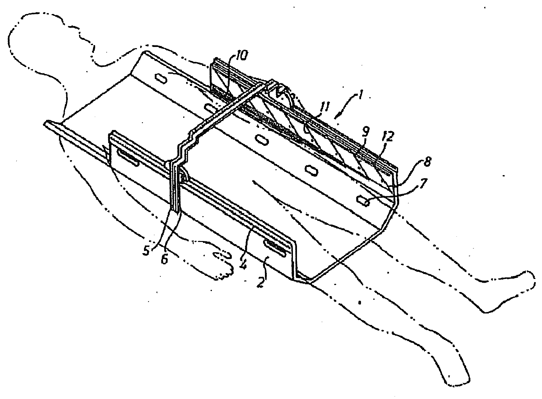
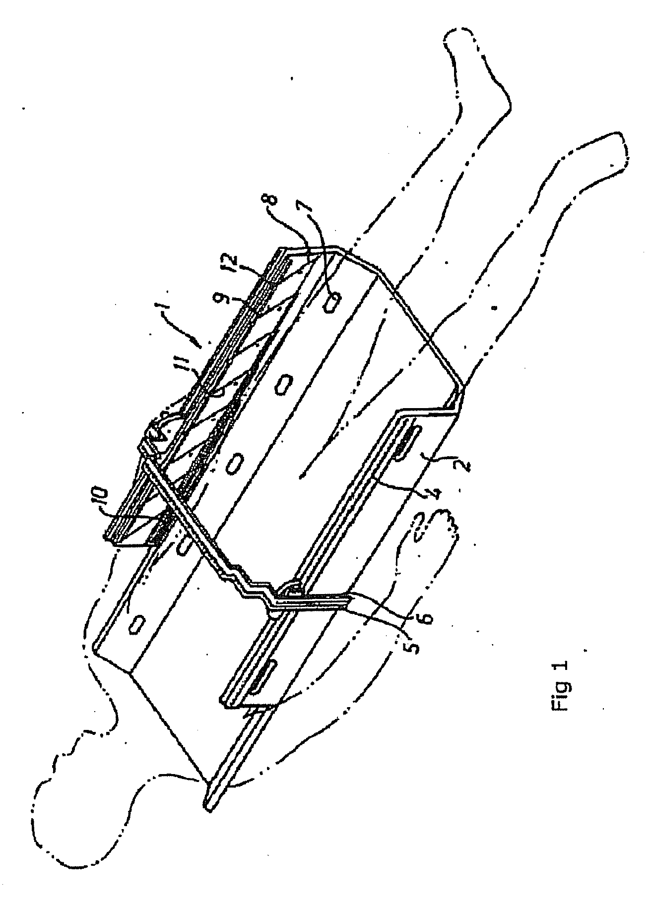
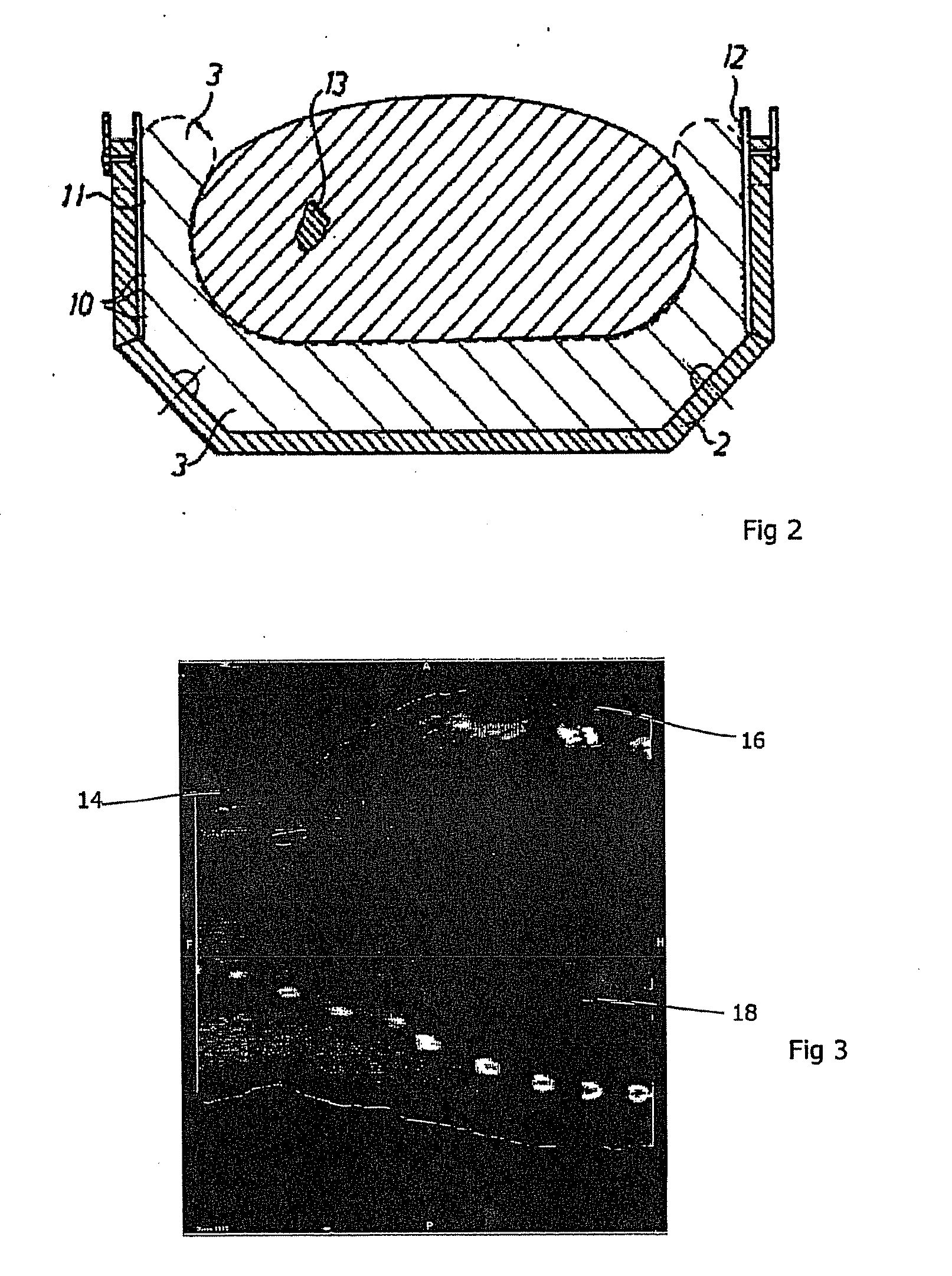
[0026]FIG. 1 shows a stereotactical body frame 1 as can be used in the present invention. This comprises an elongate, non-yielding frame 2 which is made of a material that does not cause any artefacts (disturbances) in the images, i.e., a material which is translucent to X-rays and other radioactive radiation. A fixing means 3 is adapted to be inserted in the frame 2 which is open at the top and at the ends, said fixing means comprising a flexible casing that is impermeable to fluid and hermetically encloses a yielding substance, not shown. On this fixing means, the patient is caused to take the desired position for diagnostics or treatment, the patient partially sinking into the yieldable fixing means, and a large contact surface against the patient is obtained, see FIG. 2. Subsequently, the fixing means 3 is given a non-yielding state so as to fix the patient in the desired position. This can be achieved by the casing of the fixing means holding a plurality of small bodies, for ex...


PUM


Abstract

A respiration sensor comprises a frame that is adapted to extend from a first point of contact on one side of a patient to a second point of contact on an opposing side of the patient, including a force sensor in the first point of contact. The second point of contact can comprise a patient support, which will usually support the patient in a generally horizontal state. The frame is preferably as shown in U.S. Pat. No. 5,681,326 with an arch extending over an area adapted to receive a patient. The first point of contact can include a plate which abuts the patient. The sensor is ideally located between the plate and the remainder of the frame.

Description

CROSS-REFERENCE TO RELATED APPLICATION[0001]This Application is a Section 371 National Stage Application of International Application No. PCT / EP2006 / 009700, filed Oct. 6, 2006 and published as WO 2008 / 040379 A1 on Apr. 10, 2008, the content of which is hereby incorporated by reference in its entirety.FIELD OF THE INVENTION[0002]The present invention relates to respiration monitoring.BACKGROUND ART[0003]Respiration monitoring is useful during a range of treatments, including radiotherapy. As radiotherapy involves directing harmful beams of radiation toward a tumour, it is important to minimise the dose that is applied to healthy tissue. Collimators are used to shape the beam appropriately, and the beam direction is varied over time, and these can assist in delivering the maximum dose to a tumour area and a minimum dose to healthy tissue.[0004]These measures require the location of the tumour to be known. Generally, this is established through prior investigation, but tumours near to ...

Claims


Application Information

Patent Timeline
Patent Type & Authority Applications(United States)
IPC IPC(8): A61B5/08
CPCA61B5/721A61B5/1135
Inventor WUNDERINK, WOUTER
Owner ELEKTA AB
Why Eureka
Try Eureka