Switch unit

a technology of switch unit and switch body, which is applied in the direction of switch with three operating positions, contact engagements, electrical equipment, etc., and can solve the problems of production costs increasing accordingly

Inactive Publication Date: 2008-07-24
KK TOKAI RIKA DENKI SEISAKUSHO
View PDF10 Cites 11 Cited by
  • Summary
  • Abstract
  • Description
  • Claims
  • Application Information

AI Technical Summary

Benefits of technology

[0009]According to the means described above, a click can be imparted to the rocking operation of the switching control element by the abutting portion of the movable contact and the stepped portions of the switc

Problems solved by technology

In the case of the conventional switch unit, the clicking piece 6 and the spring 5 were necessary to impart the click to the rocking operation of the switching control ele

Method used


Image

  • Switch unit
  • Switch unit
  • Switch unit

Examples


first embodiment

[0018]Hereinafter, the invention (a first mode for carrying out the invention) will be described by reference to FIGS. 1 to 4.

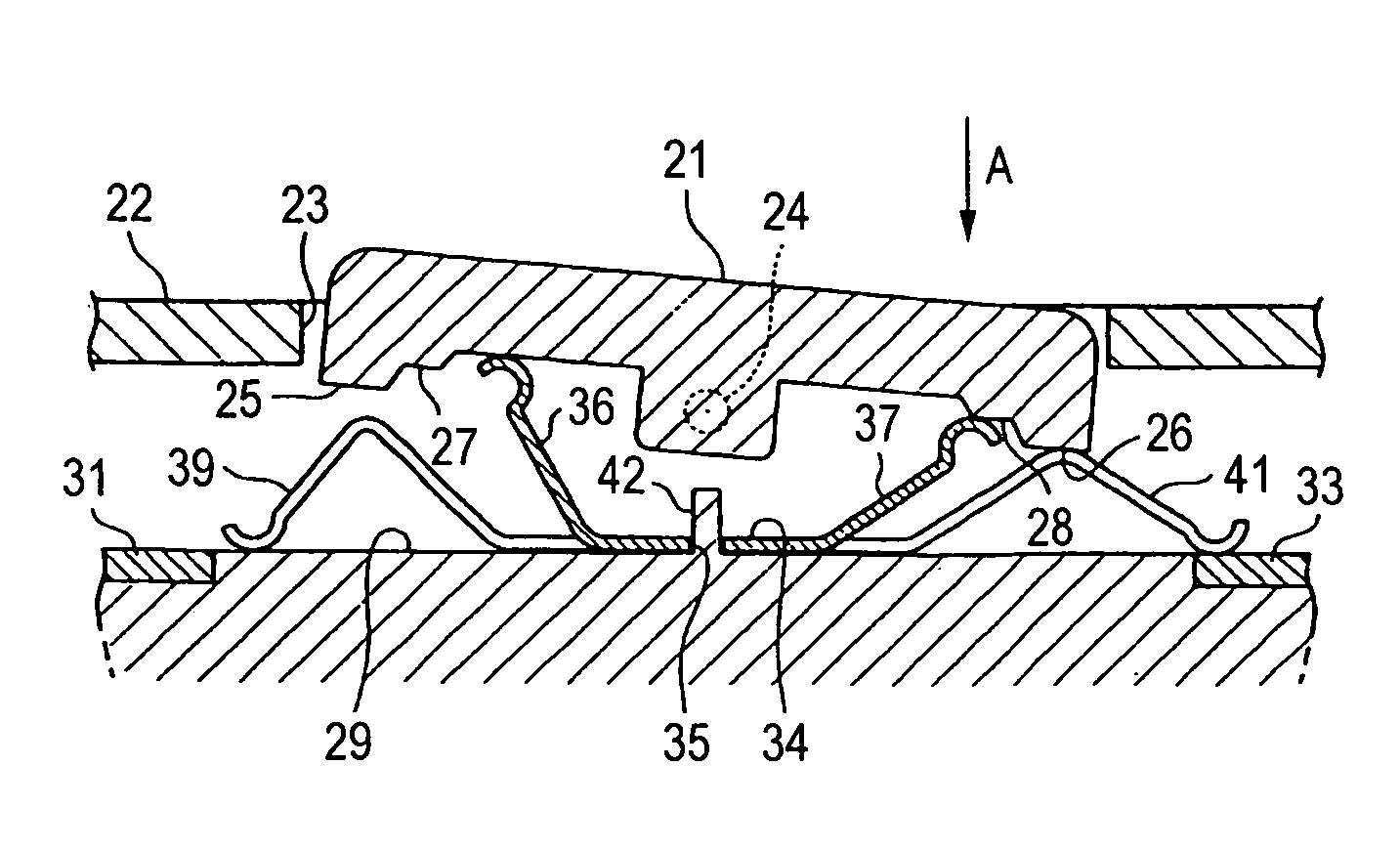
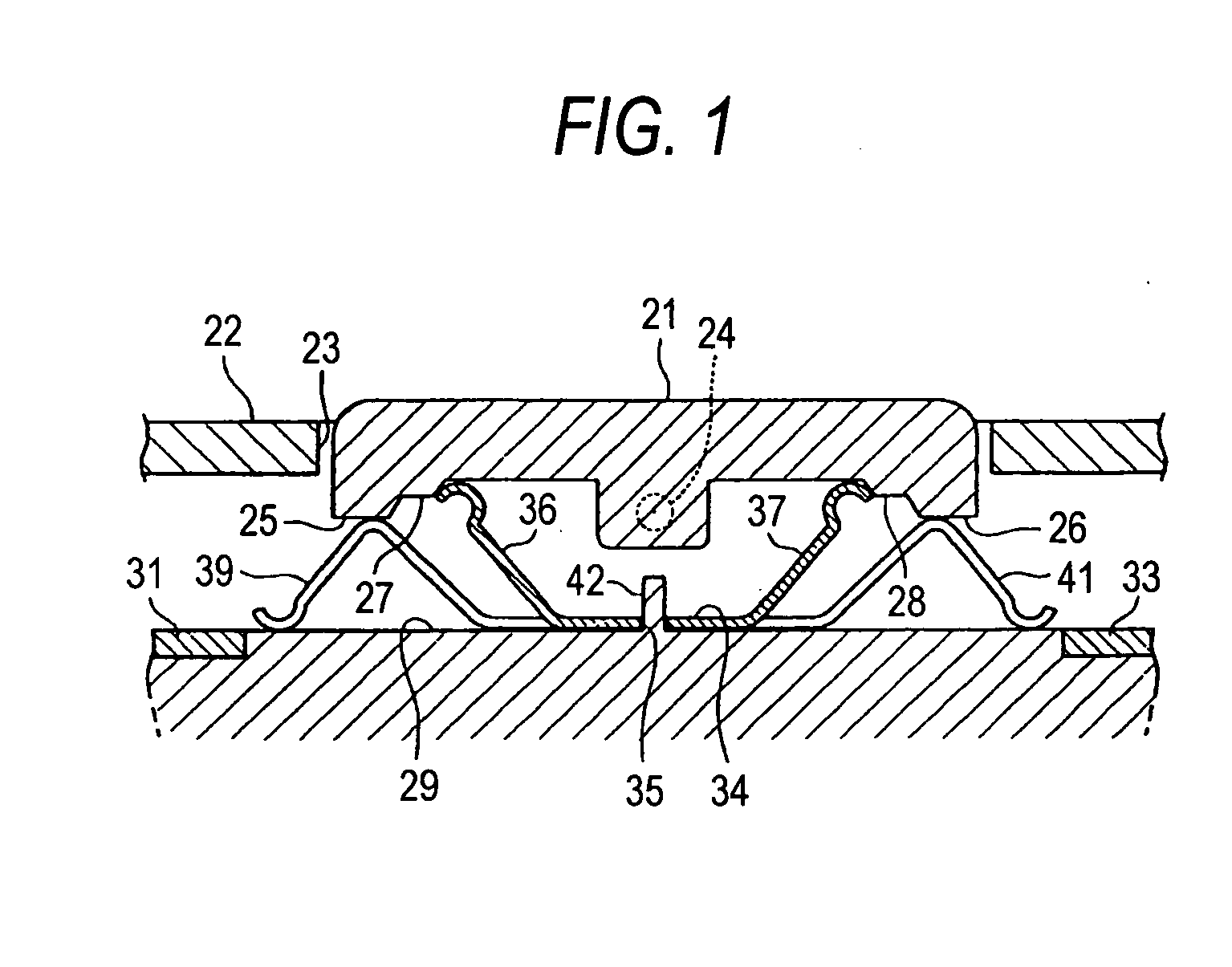
[0019]Firstly, a switching control element 21 is shown in FIG. 1, and this switching control element 21 is situated within an opening 23 in a switch case 22 and is supported on the switch case 22 at a central portion thereof by a shaft portion 24 in such a manner as to rock clockwise and counterclockwise as viewed in the figure.

[0020]Raised portions 25, 26 are formed, respectively, in left and right end portions, as viewed in the figure, on a lower surface of the switching control element 21, and stepped portions 27, 28 are formed in portions lying further inwards (towards the shaft portion 24) than the raised portions 25, 26, respectively. In this case, the raised portions 25, 26 are made to protrude further downwards than the stepped portions 27, 28.

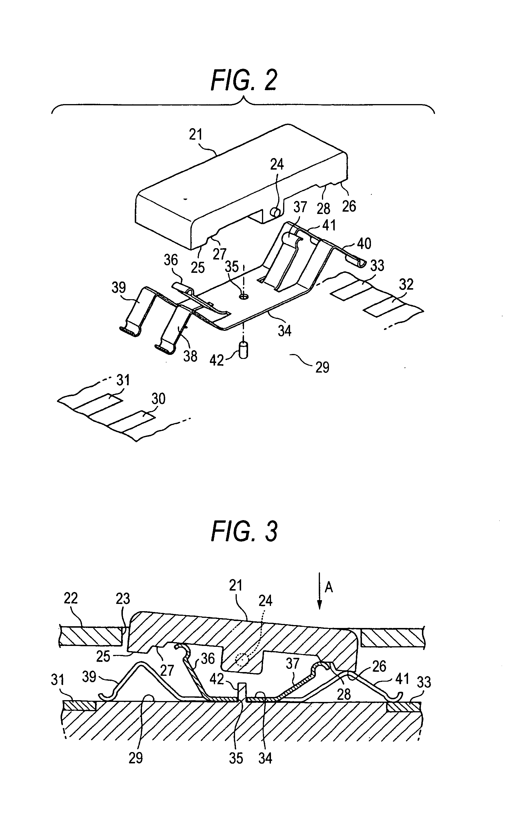
[0021]An insulator 29 is disposed below the switching control element 21, and as is also shown in FIG. 2, sta...

second embodiment

[0033]Thus, also the click can be imparted to the rocking operations of the switching control element 21 by the abutting portions 53, 54 of the movable contact 51 and the stepped portions 27, 28 of the switching control element 21, whereby since the click can be imparted to the rocking operations of the switching control element 21 without requiring the clicking piece and the spring which were required in the conventional switch unit, the number of components involved can be decreased, and hence the production costs can be decreased.


PUM


Abstract

In a switch unit, abutting portions are provided on a movable contact in such a manner as to be brought into contact with stepped portion of a switching control element, respectively, so that when the switching control element is operated to rock, the abutting portion elastically ride on the stepped portions, so as to impart a click to the rocking operation of the switching control element, whereby the click can be imparted to the rocking operation of the switching control element without requiring a clicking piece and a spring which are required in a conventional switch unit.

Description

BACKGROUND OF THE INVENTION[0001]The present invention relates to a switch unit which is improved in the construction to give a click to a switching control element which is operated to rock.[0002]Conventionally, there have been switch units which are configured as is shown in FIG. 8. In those switch units, a switch case 1 is made up of a case lower body 1a and a case upper body 1b, and a switching control element 2 is supported on the case upper body 1b of the two bodies in such a manner as to rock clockwise and counterclockwise as viewed in the figure on a shaft portion 3. The switching control element 2 has a cylindrical portion 4 below the shaft portion 3, and a spring 5 and a clicking piece 6 are accommodated in the cylindrical portion 4.[0003]A circuit board 7 is provided in such a manner as to be held between the case lower body 1a and the case upper body 1b, and pairs of stationary contacts 8, 9 are provided on the circuit board 7. In addition, a sheet 12, which is made of, ...

Claims


Application Information

Patent Timeline
IPC IPC(8): H01H15/10
CPCH01H1/40H01H23/30H01H23/143H01H1/44
Inventor ADACHI, YUKIO
Owner KK TOKAI RIKA DENKI SEISAKUSHO
Why Eureka
Try Eureka